Introduction
Power plants burning fossil fuels face some of the most stringent air emissions oversight in the United States. Under 40 CFR Part 75, federal law requires any fossil-fuel combustion unit serving a generator greater than 25 MW to install, certify, and continuously operate an approved monitoring system — compliance is a condition of operation, not an optional best practice.
The compliance picture is more demanding than many plant managers expect. Aging analyzer equipment, evolving EPA quality assurance requirements, and the strict substitute data rules that kick in during any monitoring gap create real operational and financial risk.
When a system drifts out of control, it doesn't just generate a maintenance call: it triggers conservative data substitution that can inflate reported emissions and expose the plant to permit liability.
This guide covers what CEMS is, which pollutants it must track, how the core components work, how EPA's quality assurance framework operates, and what plant engineers should evaluate when planning a system upgrade.
Key Takeaways
- 40 CFR Part 75 mandates CEMS for fossil-fuel units above 25 MW, covering SO₂, NOₓ, CO₂, and stack gas flow
- Reporting cadence: hourly data recorded continuously; quarterly electronic reports due to EPA's Clean Air Markets Division within 30 days
- RATA audits require the system to achieve ≤10.0% relative accuracy; failing triggers out-of-control status and conservative substitute data
- Flow measurement is as compliance-critical as gas concentration; without it, mass emission rates cannot be calculated
- Low-maintenance components directly reduce out-of-control data risk and the financial penalties that follow
What CEMS Is and Why Power Plants Must Have One
A Continuous Emission Monitoring System is the complete set of analyzers, flow sensors, sample handling equipment, and data software that measures stack gas pollutants in real time, producing results in the units required by the applicable emission limit. Every component in the system — analyzers, sample lines, flow sensors, data acquisition software — directly affects whether the unit meets its permit obligations.
The Regulatory Basis
EPA's 40 CFR Part 75 establishes the monitoring, recordkeeping, and reporting framework for SO₂, NOₓ, and CO₂ from fossil-fuel combustion units under the Acid Rain Program. The applicability threshold is clear: units that burn fossil fuel and serve a generator greater than 25 MW are covered. 40 CFR Part 60 Subpart Da adds NSPS obligations for large utility steam generating units capable of combusting more than 73 MW heat input, with its own subpart-specific monitoring requirements.
Units typically subject to Part 75 include:
- Coal-fired utility boilers above the capacity threshold
- Gas turbines and combined-cycle units serving generators greater than 25 MW
- Units burning higher-sulfur fuels that cannot qualify for fuel-quality alternatives
Units that may fall outside Part 75 scope include small generators at or below the 25 MW threshold and gas- or oil-fired units that qualify for fuel-flow and fuel-quality monitoring alternatives in lieu of SO₂ CEMS.
Under 40 CFR 75.10, the monitoring system must operate whenever the affected unit combusts fuel, with exceptions for scheduled calibration and maintenance windows. Quarterly electronic reports must be submitted to EPA's Clean Air Markets Division within 30 days after each calendar quarter under 40 CFR 75.64.
Beyond Compliance: The Operational Value
Real-time emission data does more than satisfy regulators. Plant operators use continuous monitoring to make operational decisions that reduce costs and prevent exceedances before they occur:
- Optimize combustion efficiency by tracking pollutant trends against fuel input in real time
- Detect process upsets early, before a minor deviation becomes a reportable exceedance
- Avoid over-dosing reagents in selective catalytic reduction (SCR) or wet scrubber systems, reducing chemical spend directly tied to emission readings
What Pollutants Does CEMS Monitor in Power Plants?
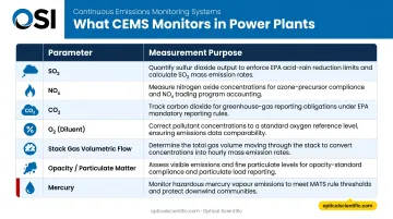
The exact parameter list depends on fuel type, unit configuration, and which regulatory subpart applies. For most fossil-fuel power units, the core monitored parameters are:
| Parameter | Measurement Purpose |
|---|---|
| SO₂ | Primary regulated pollutant under Acid Rain Program |
| NOₓ | Regulated via concentration + diluent approach |
| CO₂ | Required under CAMD program reporting |
| O₂ (diluent) | Used in emission rate calculations depending on system configuration |
| Stack gas volumetric flow | Converts concentration (ppm) to mass emission rate (lbs/hr or lbs/MMBtu) |
| Opacity / particulate matter | Required under Part 75, Part 60, or permit conditions |
| Mercury | Required for coal- and oil-fired units under MATS (40 CFR Part 63 Subpart UUUUU) |
Flow rate measurement deserves particular attention. Concentration data alone cannot satisfy Part 75 reporting requirements: volumetric flow must be measured to calculate mass emission rates. A broken or out-of-control flow sensor disables the entire mass emission calculation, not just one parameter.
All monitored parameters feed into a Data Acquisition and Handling System (DAHS). The DAHS handles four core functions:
- Records data at a minimum of one monitoring cycle per 15-minute interval
- Computes hourly averages across all monitored parameters
- Applies EPA-required unit conversion equations
- Generates standardized quarterly electronic reports for submission
How a CEMS Works: Core Components Explained
Sample Collection
A probe inserted into the stack or duct extracts a representative flue gas sample. Probe location is not arbitrary — Part 75 Appendix A includes measurement location provisions, and if relative accuracy failure can be traced to a poor sample point, the probe must be relocated. The number and placement of sampling ports also affects whether the sample is truly representative of the full stack cross-section.
Sample Conditioning (Extractive Systems)
Extracted gas travels through a heated, insulated sample line — typically PTFE-lined — to prevent condensation of moisture and compounds like SO₂ that would bias readings if they drop out of the gas phase. From there, a gas conditioning system filters particulates and either chills the sample (cold/dry extractive) or maintains it above the dew point (hot/wet extractive) before it reaches the analyzers.
Gas Analyzers
Analyzer selection depends on the pollutant and the applicable performance specification:
- SO₂, CO, CO₂: Non-dispersive infrared (NDIR) — specified under PS-2 and PS-3
- NOₓ: Chemiluminescence — covered under PS-2 and EPA Method 7E
- O₂: Paramagnetic sensing — specified under PS-3
- Particulate matter: Beta-ray attenuation or light scattering — PS-11
- Mercury: CEMS per PS-12A for MATS compliance options
Stack Gas Flow Measurement
Flow measurement is a critical, often underestimated CEMS component. Without accurate volumetric flow, no valid mass emission rate exists for reporting.
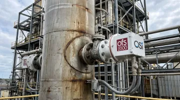
Optical cross-stack flow measurement offers meaningful advantages over pitot-based approaches. OSI's OFS-2000 Optical Flow Sensor was developed specifically for Part 75 stack gas flow monitoring. It uses patented scintillation-based technology: measuring turbulence-induced light fluctuations across the stack path rather than relying on differential pressure or sound propagation. The result is spatially averaged velocity data with ±2% accuracy across a 0–100 m/sec range, with no moving parts and no field calibration required.
Key performance characteristics of the OFS-2000:
- Deployed at major utilities including Duke Energy, Dominion Virginia Power, and Detroit Edison
- MTBF exceeds 80,000 hours
- Automatic Gain Control (OFS-2000W variant) maintains accuracy under high-opacity or particulate-laden conditions common in coal-fired stacks
Data Acquisition and Handling System (DAHS)
The DAHS is the compliance software layer that ties the system together. It collects raw signals from every analyzer and flow sensor, then handles the full compliance workflow:
- Applies EPA-required conversion equations
- Flags missing or out-of-range data
- Calculates substitute values when required
- Generates quarterly Electronic Data Reports submitted to EPA CAMD
A DAHS that cannot produce valid 15-minute cycle data, complete hourly averages, and properly formatted quarterly reports is not Part 75-compliant — regardless of how accurate the analyzers are.
In-Situ vs. Extractive CEMS: Choosing the Right Configuration
Both configurations must meet Part 75 certification and quality assurance requirements. The choice affects maintenance approach, infrastructure cost, and day-to-day operational burden.
In-situ CEMS mount analyzers directly on the stack, measuring flue gas at actual conditions without sample transport. Advantages include no sample line losses, wet-basis measurement, and simpler infrastructure. The tradeoff: instrumentation lives in a harsh environment and requires elevated-access maintenance and calibration.
Extractive CEMS withdraw the sample to a climate-controlled analyzer shelter. Two sub-types exist:
- Hot/wet extractive: sample line and analyzers stay above dew point, so no moisture correction is needed — though switching to dry-extractive later can trigger recertification
- Cold/dry extractive: sample is chilled and dried before analysis, requiring moisture correction when concentration and flow measurements use different moisture bases
Use these factors to guide your selection:
| Factor | Favors In-Situ | Favors Extractive |
|---|---|---|
| Parameter count | Few parameters | Multiple pollutants simultaneously |
| Maintenance access | Not critical | Priority — daily access needed |
| Shelter space | Limited | Available |
| Analyzer technology options | Less important | Wider choice matters |
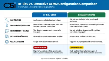
Where those factors point toward extractive, a well-designed analyzer shelter makes a real operational difference. Plants focused on minimizing staff time on compliance will find it far easier to meet the daily calibration checks Part 75 mandates from ground level than from a stack platform.
EPA Quality Assurance Requirements for Power Plant CEMS
Initial Certification
Before a CEMS can be used for compliance, it must pass a certification process demonstrating it meets the performance specifications in 40 CFR Part 60, Appendix B. For SO₂ and NOₓ CEMS, PS-2 applies; for diluent monitors, PS-3. Certification testing includes linearity checks, relative accuracy testing, and bias assessment at the specific installation.
The RATA: Annual Performance Validation
The Relative Accuracy Test Audit is the cornerstone of ongoing CEMS quality assurance. An independent testing firm installs a reference method system in parallel with the plant CEMS and runs both simultaneously. The CEMS must achieve relative accuracy within 10.0% for SO₂ pollutant concentration monitors, NOₓ-diluent CEMS, and flow monitors.
Under the Acid Rain Program, RATA is typically required semi-annually, though annual frequency applies when relative accuracy is 7.5% or less or alternative low-emitter criteria are met.
Daily Calibration Error Tests
Part 75 Appendix A requires daily calibration error (CE) checks using certified calibration gases injected at known concentrations. The CE thresholds are:
- SO₂ and NOₓ pollutant monitors: 2.5% of span
- Diluent monitors (O₂/CO₂): 0.5% O₂ or CO₂
- Flow monitors: 3.0% of span
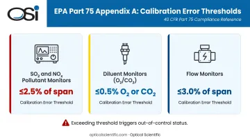
When a monitor fails its CE check, it enters "out-of-control" status. Data collected during that period is invalid, and the substitute data provisions of Part 75 Subpart D apply.
Substitute Data: The Financial Consequence of Out-of-Control Periods
When a CEMS is out of control or offline, Part 75 Subpart D mandates conservative substitute values — including 90th percentile values in specified cases. This means downtime doesn't just create a missing data problem; it can inflate reported emissions, consuming allowance balances and creating compliance exposure.
Quarterly reports to EPA CAMD must account for all operating hours, including all out-of-control and downtime periods. Minimizing these events is both a compliance and a financial priority — flow sensors are the highest-risk component because a single sensor failure corrupts the entire mass emission calculation for every pollutant tied to volumetric flow.
Planning or Upgrading a CEMS for Your Power Plant
When to Upgrade vs. Replace Components
A full system overhaul makes sense when:
- Spare parts for existing analyzers or sensors are no longer available
- The system can no longer achieve the RATA relative accuracy threshold
- The plant is adding new monitoring points (additional turbine exhaust ports, for example)
- Ongoing patchwork repairs are consuming more staff time than a new system would require
Opt for component-level replacement when the failure is isolated and the surrounding system infrastructure remains current.
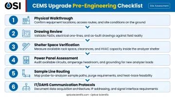
Pre-Engineering Steps
Before an Issue for Bid specification can be written, a thorough site assessment should cover:
- Physical walkthrough of the CEMS shelter, stack, and all exhaust port locations
- Drawing review — P&IDs, electrical schematics, I/O lists, and loop drawings
- Shelter space verification — rack space, climate control capacity, and utility connections
- Power panel assessment — available capacity and circuit routing
- Sample line routing — existing conduit paths and any heat trace infrastructure
- IT/DAHS communication protocols — confirming compatibility with plant SCADA or DCS systems
Selecting Components With Low Maintenance Burden
Once the site assessment is complete, component selection becomes the next critical decision — particularly for flow measurement. Every calibration event or sensor failure that puts the flow monitor out of control disables mass emission reporting for that period, with direct compliance consequences.
OSI's OFS-2000 scintillation-based flow sensor addresses this directly. Its design minimizes the maintenance interventions that trigger out-of-control periods:
- No moving parts and no field calibration requirement
- MTBF exceeding 80,000 hours
- Standard RS-232 and MODBUS RTU communication
- Optional RS-485, Ethernet, and cellular modem configurations for DAHS integration
OSI also provides field engineering and systems integration support for connecting OFS sensors into existing CEMS shelter infrastructure.
Frequently Asked Questions
What is CEMS in a power plant?
CEMS stands for Continuous Emission Monitoring System — a mandatory set of analyzers, flow sensors, and data software that measures stack gas pollutants (SO₂, NOₓ, CO₂, volumetric flow, and others) in real time. Under 40 CFR Part 75, it is a legal requirement for fossil-fuel units serving generators greater than 25 MW.
What is the function of CEMS?
CEMS serves two core functions: continuous compliance documentation (generating the hourly emission rate data reported to EPA quarterly) and operational feedback (giving plant operators real-time data to optimize combustion and minimize pollutant formation).
What is the difference between CEMS and PEMS?
CEMS uses direct physical measurement of flue gas via analyzers on or connected to the stack. PEMS (Predictive Emission Monitoring System) uses process parameters — fuel flow, load, temperature — fed into a model to estimate emissions without direct measurement, and is permitted only in limited contexts under separate EPA protocols. It is not a substitute for Part 75 CEMS where direct monitoring is required.
What gases does a CEMS monitor in a power plant?
Primary parameters include SO₂, NOₓ, CO₂, O₂ (diluent), stack gas volumetric flow, opacity or particulate matter, and mercury (required for coal- and oil-fired units under MATS, 40 CFR Part 63 Subpart UUUUU). Exact requirements vary by unit type and applicable regulatory subpart.
What is a RATA test for CEMS?
A Relative Accuracy Test Audit is an independent performance evaluation where a certified reference method runs simultaneously alongside the plant CEMS. Results are compared, and the CEMS must achieve relative accuracy within 10.0% (or applicable alternative threshold) to remain certified for compliance use.
How often does CEMS data need to be reported to the EPA?
Under 40 CFR 75.64, hourly data must be recorded continuously and submitted to EPA's Clean Air Markets Division within 30 days after each calendar quarter ends. All operating hours — including startups, shutdowns, and out-of-control periods — must be accounted for in that report.