Introduction
Oil and gas operations face some of the most demanding environmental compliance obligations in U.S. industry. Multiple federal agencies — the EPA, Bureau of Safety and Environmental Enforcement (BSEE), and Pipeline and Hazardous Materials Safety Administration (PHMSA) — require continuous, documented environmental data. Non-compliance isn't just a fine risk; it can mean stop-work orders, permit revocations, and reputational damage that follows a company for years.
The consequences are real. In 2024, the EPA and DOJ reached a $64.5 million Clean Air Act settlement with Marathon Oil — the largest stationary-source civil penalty the EPA has reported for that case. That number puts the cost of monitoring gaps in clear financial terms.
The monitoring infrastructure is where compliance is won or lost. The wrong system, a poorly maintained sensor, or a data gap at the wrong moment can trigger automatic violations — even when actual emissions are within limits. This guide covers the regulations that mandate monitoring, the system types required, the parameters you must track, and what to look for when selecting instrumentation.
Key Takeaways
- Environmental monitoring systems are regulatory infrastructure — not optional equipment — required by the EPA, BSEE, and PHMSA.
- Three rules drive most compliance obligations: EPA 40 CFR Part 60 Subpart OOOOb, 40 CFR Part 75, and the Clean Air Act.
- Covered parameters include air emissions, fugitive leak detection, and meteorological conditions.
- OOOOb continuous methane systems must detect at 0.40 kg/hr minimum and record valid readings at least once per 12-hour block.
- Civil penalties under the Clean Air Act can reach $124,426 per violation per day under current 2025 inflation adjustments.
Key Regulations Driving Environmental Monitoring in Oil & Gas
Environmental compliance obligations differ based on operation type and location. Upstream producers, midstream processors, and downstream refiners each face different regulatory frameworks — and onshore versus offshore operations fall under different agency jurisdictions.
The two primary titles of the Code of Federal Regulations (CFR) govern most monitoring requirements:
- Title 40 (Protection of Environment) — EPA rules covering emissions, air quality, and CEMS requirements
- Title 30 (Mineral Resources) — BSEE rules for offshore oil and gas operations on the Outer Continental Shelf
Emissions Standards: 40 CFR Part 60 and NSPS OOOOb
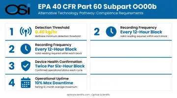
EPA's New Source Performance Standards (NSPS) under 40 CFR Part 60 Subpart OOOOb apply to new, modified, and reconstructed crude oil and natural gas facilities. Finalized in March 2024, OOOOb introduced an "Alternative Technology" pathway that allows operators to use continuous monitoring systems (including satellite-based methods) in place of traditional LDAR inspections.
To qualify under the Alternative Technology pathway, continuous systems must:
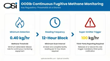
- Detect at a minimum threshold of 0.40 kg/hr methane (0.88 lb/hr)
- Record a valid methane mass emissions rate at least once every 12-hour block
- Confirm device health at least twice every six-hour block
- Maintain rolling 12-month average operational downtime of 10% or less
A separate threshold governs super-emitter events. OOOOb defines a super-emitter as any facility methane event with a quantified rate of 100 kg/hr or greater, detected by EPA-certified third parties. Those third parties must submit data to the EPA within 15 calendar days of detection. Operators must initiate investigation within 5 days of EPA notification.
Stack Gas Monitoring: 40 CFR Part 75
40 CFR Part 75 requires continuous emissions monitoring at facilities subject to the Acid Rain Program and related EPA trading programs — such as electric generating units above 25 MW, large industrial boilers, and refinery process heaters.
Covered parameters include:
- SO₂ mass emissions
- NOₓ emission rate
- CO₂ mass emissions
- Volumetric gas flow
- Opacity
- Heat input
All data must be logged, QA/QC'd, and submitted quarterly via EPA's Electronic Monitoring Compliance System (ECMPS).
Agency Roles Beyond the EPA
| Agency | Jurisdiction | Monitoring Relevance |
|---|---|---|
| BSEE | Offshore OCS operations | Safety, environmental compliance, flaring, venting |
| PHMSA | Pipeline infrastructure | Integrity monitoring, hazardous material releases |
| OSHA | All facilities | Worker exposure, process safety management |
Civil penalties under Clean Air Act Section 113(b), assessed on or after January 8, 2025, reach up to $124,426 per violation per day under 40 CFR Part 19 inflation adjustments.
Environmental Monitoring Systems Required in Oil & Gas Operations
No single system covers all compliance needs. Facilities typically deploy several system types, each determined by emission sources, applicable regulations, and site-specific permit conditions.
Continuous Emissions Monitoring Systems (CEMS)
CEMS are required at stationary sources — stacks, flares, boilers — to continuously measure pollutant concentrations and volumetric flow rates. A complete Part 75 CEMS installation includes:
- Gas analyzers for SO₂, NOₓ, CO₂, and O₂
- Stack gas flow monitoring system
- Continuous opacity monitoring (where applicable)
- Data Acquisition and Handling System (DAHS) for recording, QA/QC, and electronic reporting
- Calibration gas systems for daily calibration error tests and quarterly linearity checks
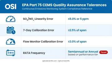
Part 75 sets precise QA tolerances that facilities must meet:
| Parameter | Requirement |
|---|---|
| SO₂/NOₓ linearity error | ≤5.0% or 5 ppm |
| 7-day calibration error | ≤2.5% of span |
| Flow monitor calibration error | ≤3.0% of span |
| Relative Accuracy Test Audits (RATAs) | Semiannual or annual, based on performance tier |
Leak Detection and Repair (LDAR) Programs
LDAR is a federally mandated protocol targeting fugitive emissions from valves, flanges, connectors, and seals. Oil and gas facilities use two primary detection approaches:
- Traditional method: EPA Method 21 portable instrument surveys or Optical Gas Imaging (OGI) cameras
- 40 CFR Part 60 Subpart OOOOb Alternative Technology pathway: Approved continuous monitoring systems meeting the 0.40 kg/hr detection threshold with 12-hour block reporting
Method 21 instruments must be capable of measuring the applicable leak definition concentration, maintain sample flow of 0.10 to 3.0 L/min, and be calibrated before each day of use.
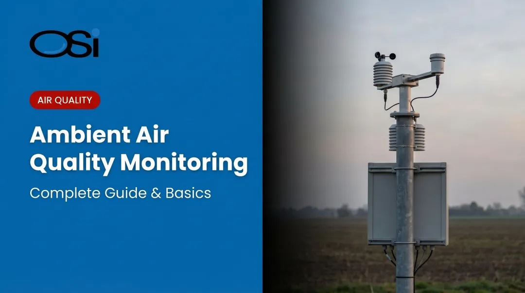
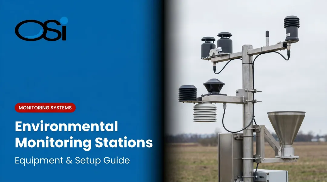
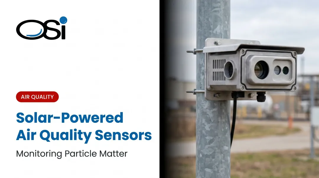
Meteorological and Atmospheric Monitoring
Refineries, tank farms, and offshore platforms need on-site meteorological monitoring for:
- Air dispersion modeling required for permit applications and renewals
- Emergency response planning and spill response scenarios
- Ambient air quality assessments tied to fenceline monitoring requirements
State and local requirements can be stricter than federal baselines. South Coast AQMD Rule 1180, for example, requires meteorological measurements as part of refinery fenceline air monitoring plans. Most permitting agencies will not accept regional weather station data as a substitute for on-site measurements in these contexts.
OSI's LOA series Long-Baseline Optical Anemometers and OWI series Weather Identifier sensors are designed for exactly these applications at refineries and petrochemical facilities, measuring crosswind velocities, atmospheric turbulence, and visibility conditions across extended facility perimeters.
Critical Parameters Your Environmental Monitoring System Must Track
Environmental compliance hinges on tracking the right parameters at the right sources. Each regulation — Part 75, OOOOb, Appendix W — targets specific pollutants, and your sensor deployment must align with your emission sources and permit conditions.
Air Emissions and Stack Gas Flow
For Part 75 compliance, facilities must continuously measure and record:
- Volumetric gas flow rate — foundational for all mass emissions calculations
- SO₂ concentration — combined with flow rate to compute mass emissions per Appendix F
- NOₓ emission rate and mass — tracked against permit limits for combustion sources
- CO₂ mass emissions — required for greenhouse gas reporting under 40 CFR Part 98
- Opacity — indicates particulate loading and combustion efficiency
Flow measurement accuracy is particularly critical. Errors in flow rate propagate directly into all mass emissions calculations — a poorly calibrated flow monitor can invalidate an entire quarterly compliance report.
Traditional pitot tube methods require regular maintenance, recalibration, and are sensitive to stack conditions like high temperatures and particulate loading. Optical flow sensing eliminates these constraints: no moving parts, no pressure drop, and measurement unaffected by temperature, gas density, or opacity changes.
OSI's OFS series — developed specifically for EPA 40 CFR Part 75 stack gas flow monitoring — uses patented scintillation-based measurement with a NIST-certified algorithm. The OFS-2000 provides a 0–100 m/sec measurement range at ±2% accuracy with no field calibration ever required.
Since deployment began in 1999, no OFS unit has recorded a calibration fault. Operators including Chevron, ExxonMobil, Shell, and Valero have deployed OFS units across refinery and industrial combustion sources.
Stack emissions are only part of the compliance picture. Fugitive sources — spread across the entire facility footprint — require a separate monitoring strategy.
Methane and VOC Fugitive Emissions
Fugitive methane and VOC monitoring targets distributed sources across the facility — storage tanks, compressor seals, pipeline connections — rather than point sources like stacks.
Key OOOOb requirements for continuous monitoring systems:
- Minimum detection: 0.40 kg/hr methane
- Reading frequency: at least once per 12-hour block
- Super-emitter threshold: 100 kg/hr triggers third-party reporting obligations
Submit data in a format regulators can validate — raw mass emissions rates, time-stamped, with documented QA/QC records.
Ambient and Meteorological Conditions
Wind speed, wind direction, temperature lapse rate, and atmospheric stability class are inputs required for air dispersion modeling used in environmental impact assessments and permit renewals.
On-site measurement is typically required because:
- EPA Appendix W requires meteorological data to be representative of the actual modeling domain
- State agencies (including California air districts) explicitly require refinery-specific meteorological stations
- Regional NWS data is often not accepted as a substitute when local terrain, land use, or industrial activity creates site-specific atmospheric conditions
Visibility monitoring adds another layer at refineries and tank farms. Fog and dust conditions affect safe vehicle and personnel movement on-site, and some state permits explicitly reference visibility thresholds as operational triggers.
How to Choose the Right Environmental Monitoring Sensors
Regulatory and Technical Selection Criteria
Sensors deployed for compliance must:
- Use EPA-approved or EPA-approvable measurement methods
- Produce data meeting Part 75 QA/QC standards (calibration error, linearity, RATA performance)
- Operate continuously with minimal manual intervention
- Include built-in continuous self-diagnostics to simplify data validation
Key specifications to evaluate:
| Specification | Why It Matters |
|---|---|
| MTBF rating | Predicts unplanned downtime risk; data gaps can trigger automatic violations |
| Operating temperature range | Refinery and flare stacks operate at extreme temperatures |
| Ingress protection | Requires NEMA 4/4X (IP66) for outdoor refinery and offshore exposure |
| No moving parts | Eliminates mechanical wear as a failure mode in high-vibration or high-particulate environments |
| Self-diagnostics | Enables continuous data validation required for regulatory reporting |
Note: IP64 does not protect against hose-directed water. For outdoor refinery and offshore exposure, IP65/IP66 or NEMA 4/4X represents the appropriate benchmark.
Why Optical Sensing Reduces Compliance Risk
The criteria above point toward a consistent conclusion: sensors that eliminate mechanical and analog failure modes outperform traditional designs in compliance-critical environments. Optical sensing addresses each of those failure modes directly:
- No moving parts — zero degradation from vibration, particulate abrasion, or thermal cycling
- Scintillation-based optics maintain measurement integrity even with dirt accumulation on the lens surface
- All-digital DSP architecture removes temperature-sensitive analog components, so readings don't drift as conditions change
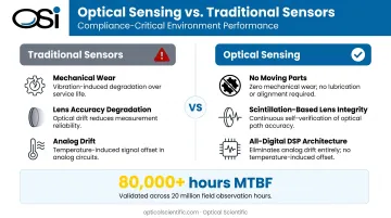
OSI's OFS series carries an MTBF exceeding 80,000 hours — validated against over 20 million hours of field observation data. That translates directly to higher data availability rates, fewer missed reporting periods, and a compliance record that holds up under regulatory scrutiny.
Building a Compliance-Ready Environmental Monitoring Program
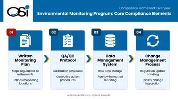
A defensible monitoring program rests on four elements:
- Written monitoring plan — maps each regulatory requirement (Part 75 parameter, OOOOb pathway, permit condition) to a specific instrument, location, and reporting frequency
- QA/QC protocol — specifies calibration schedules, acceptance criteria (referencing Part 75 Appendix A and B standards), and corrective action procedures for out-of-spec readings
- Data management system — stores raw readings, flags anomalies, and generates reports in the format each agency requires (ECMPS for Part 75, EPA notification format for super-emitter events)
- Change-management process — addresses what happens when regulations update, facility configurations change, or new emission sources are added
Each element of that framework doubles as an audit artifact. EPA and state agencies conduct surprise inspections and demand monitoring records going back multiple years. The Murphy Oil USA settlement resulted in a $1.25 million penalty and required construction of an ambient air monitoring station adjacent to the refinery — a direct consequence of inadequate monitoring infrastructure. Limetree Bay separately received an EPA enforcement notice after failing to operate five ambient SO₂ monitoring sites for significant periods.
Plan for sensor downtime. Under 40 CFR Part 75, every hour of unit operation requires a valid data record. When a monitor is unavailable, facilities must apply missing-data substitution procedures under 40 CFR 75.32 — typically substituting conservative (high) emission values.
Systems with poor reliability don't just create maintenance headaches; they inflate reported emissions and create compliance exposure even when actual emissions are within limits. An OFS series sensor with 80,000+ hour MTBF and built-in self-diagnostics that alert operators before a fault becomes a data gap is a risk management investment.
Frequently Asked Questions
What is the ISO standard for environmental monitoring?
ISO 14001:2015 is the primary international standard for environmental management systems (EMS). It provides a framework for identifying, managing, and reducing environmental impacts. ISO 14001 is not a U.S. legal requirement, but many oil and gas operators adopt it to demonstrate systematic environmental stewardship alongside EPA regulatory compliance.
What is compliance in the oil and gas industry?
Compliance means meeting all applicable federal, state, and local requirements governing emissions, waste, worker safety, and environmental protection — enforced by the EPA, OSHA, BSEE, and PHMSA. Meeting standards isn't enough; facilities must continuously document compliance through certified monitoring systems and regulated reporting.
How does the EPA monitor compliance?
The EPA uses self-reported CEMS data submitted via ECMPS, periodic facility inspections under Clean Air Act Section 114 authority, and the Methane Super Emitter Program for third-party remote detection. Falsified or missing data triggers automatic violations and significant penalties — regardless of actual emission levels.
What is 40 CFR Part 75 and why does it matter for oil and gas facilities?
Part 75 requires certified CEMS for stack gas flow, SO₂, NOₓ, and CO₂ at facilities subject to the Acid Rain Program — including industrial boilers, combustion turbines, and stationary sources at refineries and petrochemical plants. Facilities must submit quarterly electronic reports, making accurate flow measurement a non-negotiable compliance requirement.
What are the penalties for environmental monitoring non-compliance?
Under the Clean Air Act, civil penalties reach up to $124,426 per violation per day (2025 adjusted figure). BSEE and PHMSA can issue stop-work orders, suspend permits, and mandate costly remediation. Beyond fines, non-compliance triggers investor scrutiny, ESG rating impacts, and potential loss of operating licenses.
What types of environmental monitoring systems are required for oil and gas operations?
The main required system categories are:
- CEMS for stationary emission sources (stacks, flares, boilers)
- LDAR programs for fugitive emissions from equipment components
- Meteorological monitoring stations for dispersion modeling and fenceline compliance
- Ambient air quality monitoring systems for area-wide concentration tracking
Specific requirements depend on facility type, applicable NSPS subpart, and state permit conditions.