Introduction
Setting up an environmental monitoring station requires more than deploying sensors and walking away. Poor site selection skews data. Mismatched equipment causes integration failures. Skipped calibration renders readings non-compliant. Each gap compounds the next.
The stakes are real. Federal facilities can face Clean Air Act civil administrative penalties of up to $37,500 per day, per violation for noncompliance. Ambient air data that fails EPA's QA criteria gets invalidated outright, wiping out months of monitoring records.
The teams deploying these stations — environmental engineers, industrial safety groups, government agencies, DOT operations, and airport authorities — typically work under regulatory scrutiny with cross-functional coordination requirements and limited room for error.
This guide covers the full setup process: what equipment you need, how to assess and prepare a site, how to install and integrate a station step by step, and how to validate it before declaring it operational.
Key Takeaways
- Five core components are required: sensors, data loggers, communication systems, power supply, and protective enclosures
- Site selection is the most consequential early decision — no sensor upgrade can fix a poorly chosen location
- Setup follows a defined sequence: site assessment, equipment selection, physical installation, system integration, then calibration
- Optical sensors with no moving parts offer significant reliability advantages over mechanical gauges for outdoor, unattended deployments
- Post-installation calibration and validation are non-negotiable; without them, the data is unreliable
What Is an Environmental Monitoring Station?
An environmental monitoring station is a fixed or semi-portable system of sensors, data loggers, and communication equipment designed to continuously measure and record environmental conditions at a defined location. These systems feed regulatory compliance programs, operational decision-making, and long-term research — and data accuracy and system uptime are non-negotiable.
The EPA's Air Quality System (AQS) stores data from over 10,000 monitors, with roughly 5,000 currently active. NOAA's ASOS network alone operates more than 900 continuous observation sites across the U.S. Stations built to these standards are expected to contribute reliably to networks at that scale.
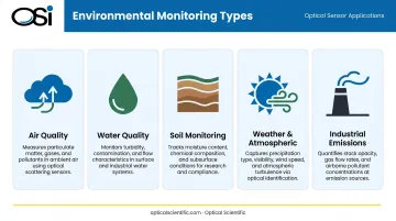
The Five Primary Monitoring Types
Most stations are designed to serve one or more of these functions:
- Air quality monitoring — particulate matter, gases, NAAQS compliance
- Water quality monitoring — surface water, groundwater, discharge points
- Soil monitoring — temperature, moisture, nutrient conditions
- Weather and atmospheric monitoring — temperature, wind, precipitation, visibility
- **Industrial emissions and compliance monitoring** — stack gas flow, continuous emission monitoring systems (CEMS)
Many deployments combine types. An airport station, for example, may measure precipitation, visibility, wind, and present weather simultaneously.
Core Equipment for Environmental Monitoring Stations
Equipment selection must start with the monitoring objective — the parameters to be measured, the regulatory framework, and the environmental conditions the station will face. Generic off-the-shelf bundles routinely fail because they don't account for site-specific factors.
Environmental Sensors
Sensor categories span a wide range of measurement needs:
- Atmospheric sensors — temperature, humidity, barometric pressure, wind speed and direction
- Precipitation sensors — rain gauges, optical disdrometers, all-precipitation gauges
- Visibility and present weather sensors — optical weather identifiers, forward scatter sensors
- Air quality sensors — particulate matter analyzers, gas analyzers
- Soil and water quality probes — temperature, moisture, dissolved oxygen, conductivity
Sensor technology type has real consequences for outdoor, unattended stations. A 2023 peer-reviewed review identified tipping-bucket rain gauge measurement uncertainty from calibration errors, high-intensity rainfall undercatch, mechanical bucket behavior, clogging, evaporation, wetting losses, and wind effects — all inherent to the mechanical collection principle.
Optical sensors avoid these failure modes entirely. OSI's scintillation-based sensors, for example, measure precipitation instantaneously as it falls through an infrared optical beam rather than collecting water. This eliminates evaporation error, wind-induced measurement loss, and clogging.
AI algorithms automatically compensate for dust, water droplets, or ice on the lenses — so no scheduled cleaning is required. OSI's optical sensors carry an MTBF exceeding 80,000 hours, validated across deployments ranging from Antarctic research stations to FAA airport systems and highway RWIS networks.
Data Loggers and Controllers
The data logger is the station's central processing hub. It collects sensor outputs, applies time stamps, runs onboard QA algorithms, stores data, and manages transmission. Per WMO-No. 8 guidance, AWS data loggers should include a 24-hour real-time clock — ideally GPS-synchronized — along with onboard buffering for transmission continuity.
Key selection criteria:
- Input compatibility with your chosen sensors (SDI-12, RS-232, RS-485, 4-20mA)
- Onboard storage for data continuity during communication outages
- Operating temperature range for the deployment environment
- Support for QA/QC flagging, including flatline detection and out-of-range alerts
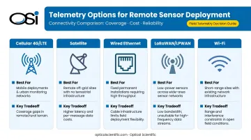
Communication and Telemetry Systems
| Option | Best For | Tradeoffs |
|---|---|---|
| Cellular (4G/LTE) | Remote stations with cellular coverage | Ongoing data costs; requires SIM management |
| Satellite | Remote sites with no cell coverage | Higher cost, latency |
| Wired Ethernet | Fixed infrastructure sites | Reliable; requires cabling |
| LoRaWAN / LPWAN | Low-power, low-bandwidth applications | Limited data rate; range dependent on environment |
| Wi-Fi | Short-range facility monitoring | Limited range outdoors |
NOAA ASOS stations report hourly, with special observations when thresholds are exceeded. AWOS systems typically report at 20-minute intervals. Your communication architecture must match your data latency requirements.
Power Supply
WMO-No. 8 specifies that AWS power supplies require high stability and interference-free operation, with 12V DC battery configurations float-charged from mains power. For remote stations, solar panels with battery backup are standard.
Size the power system for worst-case conditions:
- Extended cloudy periods (not average solar irradiance)
- Peak sensor draw during active sampling cycles
- Communication transmission loads, which spike current draw
- Backup continuity requirements for compliance-critical deployments
Protective Enclosures and Mounting Hardware
Key requirements for enclosures and mounting hardware:
- IP rating: Minimum IP54 for most outdoor deployments; IP64 or higher for harsh or high-humidity environments (per IEC 60529)
- Lightning protection: NFPA 780 compliance required for exposed fixed stations — this should be engineer-designed, not an afterthought
- Structural loading: Mounting structures must account for wind load, frost heave, and vandalism risk
- Sensor placement: Enclosures must not obstruct airflow around sensors, create localized heat signatures, or introduce RF interference — any of these will corrupt data at the source
How to Set Up an Environmental Monitoring Station
Successful station setup follows a defined sequence. Deviating from this order, particularly by rushing calibration or skipping the site assessment, is the primary cause of poor data quality and expensive rework.
Prerequisites and Site Assessment
Before ordering any equipment, confirm:
- The area the station must represent — urban, industrial, rural, or facility perimeter
- Absence of local obstructions that would bias readings — buildings, exhaust stacks, trees, heat sources
- Regulatory siting requirements — these must be reviewed before procurement
Siting requirements are specific and quantified. 40 CFR Part 58 Appendix E specifies probe heights of 2.0–15.0 m for neighborhood-scale ozone and SO₂ monitors, a minimum 10 m clearance from tree drip lines, and at least 270 degrees of unrestricted airflow.
WMO-No. 8 requires wind sensors at 10 m height over level, open terrain with obstructions placed at least 10 times their own height away. Precipitation gauges must be separated from nearby objects by at least twice the object height.
Non-negotiables before procurement:
- Power and communications infrastructure confirmed available, or a remote-power plan finalized
- Applicable regulatory siting criteria reviewed and documented (EPA, FAA AC 150/5220-16E, WMO)
- Ground conditions and structural requirements assessed for mounting
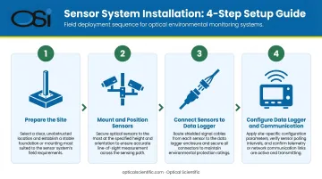
Step-by-Step Station Installation
With site readiness confirmed, installation can proceed in four defined steps.
Step 1 — Prepare the site Install the mounting structure (mast, tripod, or equipment shelter foundation), run conduit for cabling, confirm grounding and lightning protection are in place. Verify the site matches the pre-assessment plan before unpacking any sensors.
Step 2 — Mount and position sensors Install sensors per manufacturer siting specifications — height above ground, separation distances from obstructions, correct orientation for wind and precipitation sensors. Confirm no sensor sits in the turbulent wake of another.
Step 3 — Connect sensors to the data logger Wire or configure each sensor to the data logger according to the wiring diagram. Confirm correct input channel assignment, document all connections, and verify total power draw is within the power system's capacity.
Step 4 — Configure the data logger and communication system Set sampling intervals, engineering unit conversions, QA/QC threshold flags, and data transmission schedules. Configure authentication for the telemetry link. Confirm data is reaching the receiving end — server, SCADA, or cloud platform — before closing the installation.
Post-Installation Validation
Validation confirms the station is performing correctly before it's declared operational. EPA guidance is explicit: data failing critical QA criteria is invalidated regardless of how well the hardware was installed.
Key validation checks:
- Run the station for the manufacturer-specified stabilization period
- Cross-check readings against a co-located reference instrument or portable calibration standard
- Confirm all sensor outputs are within manufacturer-specified accuracy tolerances
- Inspect all physical connections for weather ingress; confirm enclosure seals are intact
- Verify solar charging is functioning correctly (for remote stations)
- Test communication failover if redundant links are configured
- Review initial data files for flat-lined channels, unrealistic spikes, or offset readings
For EPA-regulated air monitoring, 40 CFR Part 58 Appendix A specifies gaseous one-point QC checks at least every two weeks, monthly PM2.5 flow checks, and semiannual flow audits. Build this schedule into the station's operational plan before going live.
Common Setup Problems and How to Fix Them
Most post-installation problems fall into one of three categories — and each has a straightforward fix.
Sensor Output Errors or Flat-Lined Channels
Problem: One or more channels show constant values or clearly incorrect readings immediately after installation.
Likely cause: Incorrect wiring to data logger input channels, incompatible signal type (for example, a 4-20mA sensor connected to a voltage input), or incorrect power supply voltage at the sensor.
Fix: Work through these checks in order:
- Verify wiring against the sensor data sheet and data logger input configuration
- Check supply voltage directly at sensor terminals
- Confirm input channel type settings in the data logger configuration
Communication Link Failures
Problem: The station isn't transmitting data, or is transmitting intermittently.
Likely cause: Incorrect APN or server credentials in the cellular modem, antenna placed inside a metal enclosure causing signal loss, or insufficient power during transmission cycles.
Fix: Verify modem configuration settings, move the antenna to an external mount, and measure current draw during a transmission cycle to confirm the power system can support the load.
Calibration Drift Detected During Validation
Problem: Sensor readings differ from the reference instrument beyond acceptable tolerance, or shift over the first days of operation.
Likely cause: The most common culprits are shock or temperature extremes during shipping, factory calibration not verified before installation, or sensors that require a break-in stabilization period.
Fix: Allow the full manufacturer-specified stabilization period before running calibration checks. If drift persists beyond tolerance after stabilization, return the sensor for recalibration — don't declare the station operational until readings are within spec.
Pro Tips for a Reliable Environmental Monitoring Station
Specify sensors with built-in self-diagnostics. Remote identification of sensor degradation before data quality is compromised is the difference between proactive maintenance and emergency rework. OSI's optical sensors run continuous internal self-tests that update once per minute and report any potential problems directly in the output message — so operators can flag issues before scheduling a site visit.
Build maintenance access in from the start. Stations optimized for measurement but not for access routinely accumulate calibration drift or go offline entirely. Before the station enters service, establish:
- Defined intervals for sensor inspection and calibration verification
- A schedule for enclosure checks and connector integrity review
- A spare parts inventory stocked ahead of first operation
Frequently Asked Questions
What is an environmental monitoring station?
An environmental monitoring station is a fixed or portable system of sensors, data loggers, and communication equipment designed to continuously measure and record environmental conditions — such as air quality, weather, precipitation, soil, or emissions — at a defined location. These stations support regulatory compliance, operational safety decisions, and environmental research.
What are the 5 types of environmental monitoring?
The five main types are air quality monitoring, water quality monitoring, soil monitoring, weather and atmospheric monitoring, and industrial emissions and compliance monitoring. Many stations are configured to support more than one type simultaneously depending on the application.
What equipment is needed for an environmental monitoring station?
The five core components are environmental sensors matched to the parameters being measured, a data logger or controller, a communication and telemetry system, a power supply (grid or solar-battery), and a protective enclosure with appropriate mounting hardware.
How do you power a remote environmental monitoring station?
Remote stations most commonly use solar panels paired with battery banks, sized for worst-case low-sun periods and peak power draw from sensors and communication systems. Some applications use wind turbines or hybrid configurations. Backup power continuity is essential for compliance-critical deployments where data gaps can trigger regulatory consequences.
How often do environmental monitoring stations need to be calibrated?
Calibration frequency depends on sensor type and regulatory requirements. EPA's 40 CFR Part 58 Appendix A requires gaseous one-point QC checks at least every two weeks and semiannual PM2.5 flow audits. For unattended outdoor stations, best practice is a calibration check at every scheduled maintenance visit and after any event (storm, power outage, or physical disturbance) that may have affected sensor performance.
What are the most common mistakes when setting up an environmental monitoring station?
The four most common mistakes are:
- Poor site selection that introduces systematic bias into readings
- Skipping post-installation calibration validation
- Undersizing the power system for peak load and worst-case solar conditions
- Failing to document the installation configuration
Any of these can produce unreliable data, regulatory non-compliance, or costly rework.