Introduction
At sea, wind isn't just a weather variable—it's a direct control input. During a port approach, a 40-knot crosswind doesn't give a ship handler time to consult a forecast. It demands real-time data at the bridge, updated continuously, accurate enough to make a go/no-go call before the vessel commits to the channel.
The problem is that most traditional anemometers aren't built for that demand. Moving parts corrode in salt air. Bearings wear under constant vibration, and offshore maintenance access is limited at best. The result: gaps in wind data precisely when that data matters most.
This article covers:
- Why continuous wind monitoring is operationally critical
- Which vessel types and scenarios depend on it most
- How the major sensor technologies compare
- What specifications to prioritize when evaluating a maritime wind monitoring system
Key Takeaways
- Real-time wind data is a safety-critical input during berthing, offshore station-keeping, cargo lifting, and flight deck operations—not a weather advisory.
- Salt spray, humidity, and vibration accelerate sensor failure—no-moving-parts designs hold a clear reliability advantage in marine environments.
- Four sensor categories serve maritime wind monitoring: mechanical anemometers, ultrasonic sensors, lidar systems, and optical scintillation-based sensors.
- Wind data is only operationally useful when it integrates cleanly with navigation displays, DP computers, and WASP optimization platforms.
- Buyers should verify MTBF ratings, ingress protection, communication protocol compatibility, and relevant classification society requirements before specifying a system.
Why Remote Wind Speed Monitoring Matters in Maritime Operations
Wind Forces Are Larger Than They Appear
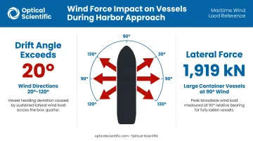
A vessel moving at slow speed through a harbor has minimal hydrodynamic control authority. Wind becomes the dominant lateral force. Research on a RoRo passenger ferry found that drift angle can exceed 20 degrees for wind directions between 20 and 120 degrees, with required rudder angles exceeding the 35-degree physical limit when the wind-speed-to-ship-speed ratio reaches 20 or more. For a large container vessel—UASC Barzan at 400 meters LOA with 17,583 m² of lateral wind area—modeled lateral force at 90-degree wind reached 1,919 kN in non-uniform flow conditions.
These aren't edge cases. They're the conditions vessels routinely encounter during port approach.
Periodic weather readings or forecasts cannot capture this. A gust that builds over 90 seconds between observation intervals can decide whether a berthing maneuver stays controlled. Continuous monitoring gives the bridge team the margin to respond—or to call for an extra tug before it's needed.
The Marine Environment Destroys Sensors
The challenges that make wind monitoring hard are exactly the challenges that degrade the sensors used to provide it:
- Salt fog accelerates corrosion of bearing assemblies, contact surfaces, and exposed electronics
- High humidity degrades unprotected circuitry and creates condensation inside sensor housings
- Constant vibration loosens mechanical assemblies and fatigues moving components
- Biofouling and debris blocks rotating cups and vane pivots
An IMCA safety flash documented a DP drive-off where water ingress from a failed junction box seal caused a wind sensor reading of 5–10 knots actual wind to be misreported as 60 knots. The DP computer averaged the two sensor inputs and received a 35-knot signal—enough to drive the vessel 17 meters from set point before the bad sensor was deselected.
Wind sensor failure isn't a maintenance inconvenience. In a DP context, it directly causes positioning incidents—a distinction that regulators have translated into binding requirements.
Regulatory Context
Several frameworks set minimum wind monitoring standards, spanning DP vessel operations, voyage data recording, and offshore helidecks:
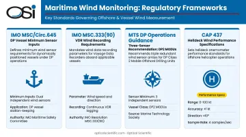
- IMO MSC/Circ.645 specifies that DP vessels should measure heading, vessel motions, and wind speed and direction as minimum sensor inputs
- IMO MSC.333(90) requires VDRs to record wind speed and direction (true or relative) where a suitable sensor is fitted, for systems installed from July 1, 2014
- Marine Technology Society DP Operations Guidance recommends three wind sensors for DP2 MODUs, noting mechanical and ultrasonic sensors can diversify common-mode failure risk
- CAP 437 sets offshore helideck wind sensor performance standards, including:
- 0–100 knot operating range
- Speed accuracy of ±1 knot (or ±10% above 10 knots)
- Direction accuracy better than ±10 degrees above 2 knots
- Minimum 4 samples per second for 3-second gust capture
Key Maritime Use Cases for Wind Speed Monitoring
Port and Harbor Approach
Berthing is where wind monitoring has the clearest safety record. Port Authority NSW Shiphandling Safety Guidelines set explicit thresholds: vessels up to 240 meters LOA are generally handled up to 35 knots, while vessels over 240 meters are not moved in winds exceeding 25 knots. For Wilhelmsen RoRo vessels, tug requirements escalate from two tugs below 20 knots sustained to three tugs between 20 and 25 knots, with no movement permitted above 25 knots.
The MAIB investigation into the Pride of Kent grounding at Calais found that wind had increased to 40–50 knots on the starboard quarter during approach, with gusts reaching 70 knots at the moment of grounding. Real-time monitoring at bow, midship, and stern positions gives pilots and captains the data to make those tug and approach decisions before the vessel is committed.
Dynamic Positioning Systems
DP computers use wind as a feed-forward disturbance input, estimating the force thrusters need to counteract before position error develops. When wind data is wrong, the DP model is wrong, and the system either over- or under-compensates. The IMCA drive-off case described above is the result: a false high-wind reading drives unnecessary thruster response that pushes the vessel off station.
Regulatory and industry guidance establishes clear requirements for DP wind sensor integration:
- IMO MSC/Circ.645 mandates wind sensor input as a formal DP system requirement
- MTS guidance requires a difference alarm when sensors produce divergent readings, triggering immediate operator assessment
- Sensor quality, redundancy, and failure behavior all matter — not just whether a sensor is installed
Wind-Assisted Ship Propulsion (WASP)
Lloyd's Register reported approximately 100 WASP installations in 2024, with 72 units in the orderbook. DNV noted that 75% of the installed fleet as of February 2025 consisted of retrofits, primarily on tankers and general cargo vessels.
For these vessels, wind monitoring drives the fuel savings calculation. MARIN's research framework indicates demonstration projects have shown 5–15% fuel and emissions savings are immediately achievable in average wind conditions. Those savings depend entirely on knowing what the wind is actually doing across the vessel's wind profile, not just at mast height.
The MARIN/Vaisala trial aboard MV Ankie on March 24, 2021, approximately 40 NM off the Netherlands, demonstrated how scanning lidar can capture full 3D wind field data around WASP equipment, revealing the undisturbed wind profile that point sensors cannot provide. That data feeds routing optimization algorithms that calculate optimal sail angles and recommend course corrections.
Cargo Lifting and Offshore Operations
Offshore crane and lifting operations are governed by project-specific wind limits set by marine warranty surveyors under frameworks like DNV-ST-N001. Wind monitoring allows operations to proceed up to those limits with confidence, rather than shutting down early due to uncertainty about actual conditions.
Naval and Military Maritime Operations
The same precision that matters in civilian lifting operations is even more critical on naval platforms. Flight deck operations, weapons system safety envelopes, and close-quarters maneuvering all depend on accurate, continuous wind data. OSI's no-moving-parts optical sensors are trusted by the U.S. Navy, NASA, NOAA, and the FAA, confirming that this sensor architecture meets the reliability demands of military maritime environments.
Types of Wind Sensors Used in Maritime Environments
| Sensor Type | Strengths | Maritime Limitations |
|---|---|---|
| Mechanical (cup/vane) | Long track record, low cost, adds DP sensor diversity | Corrosion, bearing wear, biofouling, ice imbalance, recalibration burden |
| Ultrasonic | No moving parts, low maintenance, fast response | Can share common-mode environmental failure risks; some models affected by heavy icing |
| Lidar | 3D wind field data, far-field measurement for WASP | High cost, research/validation use rather than routine bridge instrument |
| Optical scintillation | No moving parts, path-averaged measurement, continuous diagnostics, proven in harsh marine environments | Crosswind component measurement rather than full 3D wind vector |
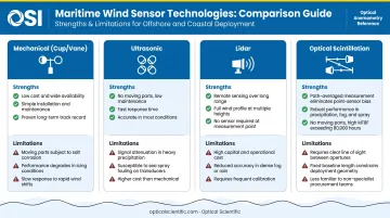
Mechanical Anemometers
Cup and vane anemometers have decades of service history and low unit costs. Their limitation in maritime service is clear: every moving part is a failure point, and saltwater accelerates failure. Bearings fatigue, cups corrode, and vanes seize. Inspection and replacement require personnel and access that offshore vessels often can't provide for weeks at a time. MTS guidance acknowledges this, noting that mechanical sensors can nonetheless add diversity value in DP configurations where ultrasonic sensors dominate.
Ultrasonic Anemometers
Ultrasonic sensors measure wind speed and direction through the time-of-flight of sound pulses between fixed transducers—no moving parts, no wear. They respond faster than mechanical sensors and require significantly less maintenance. The trade-off is that some models perform poorly in icing conditions, and in DP configurations, multiple ultrasonic sensors can share common environmental failure modes, which is why MTS guidance recommends mixed sensor types for critical DP vessels.
Lidar Wind Sensors
Lidar scans a wind volume remotely using laser pulses, generating 3D wind field data across a spatial area rather than a single measurement point. This makes it valuable for WASP research and offshore wind assessment, where understanding the vertical and horizontal wind structure around the vessel matters. For routine bridge and DP wind input, lidar hasn't been established as a replacement for shipboard point sensors—it remains primarily a research and validation tool.
Optical Scintillation-Based Sensors
Optical scintillation sensing detects wind-induced variations in air density along an optical beam path, measuring crosswind velocity and atmospheric turbulence without any moving parts. The measurement is path-averaged over the full beam length—from 100 meters to over 10 kilometers—rather than a single-point sample.
OSI's LOA (Long-Baseline Optical Anemometer) series uses this principle. The LOA-005 is built for environments where maintenance windows are rare:
- AGC circuitry compensates for contaminated optics, LED output variations, and dust
- Continuous internal diagnostics with no scheduled calibration required
- MTBF exceeds 80,000 hours
OSI's optical instruments have been deployed on NOAA data buoys in the Gulf of Mexico and Pacific Ocean, on NASA research vessels, and on 3m Discus series buoys in the North Atlantic, where Wood plc reported the OWI-650 "performed extremely well over the past few years."
What to Look for in a Maritime Wind Monitoring System
Environmental Ruggedness
Maritime sensors need to survive salt fog, moisture ingress, UV exposure, and mechanical vibration—not just for days, but for months between service intervals. Key ratings to verify:
- IP65 or IP66 ingress protection (dust-tight; protected against water jets or powerful jets)
- CE marking for electromagnetic compatibility
- ISO 9001:2015 quality system certification
- Evidence of marine environmental testing beyond IP rating alone—IP classification covers ingress protection, not corrosion resistance in salt spray
OSI's sensors carry CE and ISO 9001:2015 certifications, with field validation across North Atlantic buoy deployments and NOAA research ship installations.
Reliability and MTBF
Offshore and long-voyage operations may go weeks or months without access to qualified maintenance personnel. When evaluating vendors, look for:
- Documented MTBF data from field deployments, not just theoretical calculations
- MTBF exceeding 80,000 hours as a practical threshold for offshore reliability
- Built-in continuous self-diagnostics that report faults through the standard data output
OSI's LOA series meets this threshold, with internal diagnostics monitoring performance around the clock.
Communication Protocol Compatibility
Wind data is only useful when it reaches the systems that need it. Maritime bridge and DP systems typically communicate via:
- NMEA 0183 (IEC 61162-1): the standard single-talker/multiple-listener serial protocol for navigation electronics
- NMEA 2000 (IEC 61162-3): network-based protocol for SOLAS vessel applications
- RS-422 / RS-485: common serial interfaces in industrial and bridge system integrations
OSI's LOA series supports RS-232 as standard and RS-485 as an optional configuration, along with Ethernet and MODBUS RTU. For NMEA protocol compatibility or custom interface requirements for DP or navigation platform integration, contact OSI's technical team directly for application-specific configuration.
Integration with Onboard Maritime Systems
Wind data doesn't operate in isolation. The path from sensor to decision runs through multiple downstream systems, and the quality of that data determines the quality of every output that depends on it.
The Data Chain
A typical integration path looks like this:
- Sensor measures wind speed and direction continuously
- Protocol output (RS-485, NMEA 0183, Ethernet) transmits data to bridge network
- Navigation displays show real-time apparent and true wind for the officer of the watch
- Autopilot system uses wind input to adjust heading hold parameters
- DP computer incorporates wind as a feed-forward environmental disturbance signal
- Voyage management platform logs wind data for post-voyage analysis and regulatory reporting
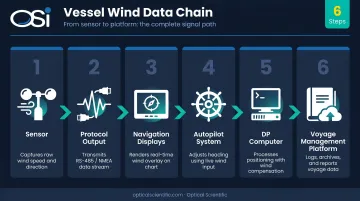
A sensor that produces noisy, intermittent, or incorrect data doesn't just create a local problem—it propagates errors through every downstream system simultaneously. The IMCA DP drive-off case makes this concrete: one bad sensor signal, averaged with a good one, put a vessel 17 meters off station.
WASP and Voyage Optimization Integration
Vessels using wind-assisted propulsion feed wind sensor data into routing optimization software that calculates optimal sail angles, recommends course adjustments, and quantifies fuel savings against voyage benchmarks. Norsepower and NAPA have announced integration of voyage optimization tools for wind-assisted vessels specifically for this purpose.
Routing algorithms are only as good as the wind data they consume. A sensor error of a few degrees in wind direction or a few knots in speed shifts the calculated optimal heading and distorts predicted fuel savings.
For WASP operators, wind monitoring isn't just a safety instrument. It's the measurement basis for demonstrating regulatory compliance with:
- EEDI (Energy Efficiency Design Index)
- EEXI (Energy Efficiency Existing Ship Index)
- CII (Carbon Intensity Indicator) annual ratings
Frequently Asked Questions
What is an anemometer in maritime?
A maritime anemometer is an instrument installed on a vessel or port structure to measure wind speed and direction in real time. Bridge teams use this data for navigation decisions, maneuvering in confined waters, compliance with port-specific wind limits, and safe cargo operations.
What are the three types of anemometers?
The three main types are mechanical (cup and vane), ultrasonic (time-of-flight sound pulses between fixed transducers), and optical/remote sensing systems including lidar and scintillation-based sensors. Optical and ultrasonic designs are generally preferred for maritime use because they have no moving parts exposed to salt spray and corrosive air.
What is the difference between apparent wind and true wind on a vessel?
Apparent wind is what the sensor measures—the vector combination of actual wind and the vessel's own movement through the air. True wind is the actual wind independent of vessel motion. Navigation systems and WASP platforms calculate true wind by combining apparent wind readings with vessel speed and heading data.
How do wind sensors integrate with dynamic positioning systems?
Wind sensors feed real-time data directly into the DP computer, which uses it to estimate the forces thrusters must counteract to hold station. Inaccurate or delayed readings cause the DP model to over- or under-compensate, raising fuel consumption and introducing positioning error.
What certifications should a maritime wind sensor have?
At minimum, look for IP65 or higher ingress protection, CE marking for electromagnetic compatibility, and ISO 9001:2015 quality certification. Vessel class and operating region may also require approval from classification societies such as DNV, Lloyd's Register, or ABS.