Introduction
Getting power to a sensor on a mountain ridge, a highway corridor in Wyoming, or a data buoy in the North Atlantic is frequently the hardest engineering constraint in any remote deployment. You can't run a cable to the middle of nowhere, and battery-only systems eventually require someone to drive or hike out for a swap.
Solar power solves this by creating a self-replenishing energy source that, when paired with the right storage, keeps sensors running continuously across seasons — no fuel deliveries, no battery swaps, no unplanned outages.
USGS documented that approximately 14% of streamgages went offline due to telemetry-system issues — a reminder that power and communications are a single uptime problem, not separate ones.
This guide covers: key hardware components, a five-step sizing methodology, low-power design principles, real-world application examples, and the field challenges that take systems offline.
Key Takeaways
- Solar plus battery storage is the standard solution for unattended remote sensor deployments
- Size your panel using: (daily Wh load ÷ Peak Sun Hours) × system loss factor
- Always size for worst-case winter sun, not annual averages
- Duty cycling and low-power wireless protocols (LoRaWAN preferred) are as important as panel size
- OSI's OWI, APG, and OFS sensor lines run on nominal 12 VDC at ≤400 mA, compatible with standard solar-charged battery systems
Why Remote IoT Sensors Need Dedicated Solar Power Solutions
Running grid power to isolated field locations is expensive, often impractical, and introduces its own failure points. Battery-only deployments reduce installation cost but shift the burden to recurring site visits — every swap is a scheduling problem, a labor cost, and a potential data gap.
Peer-reviewed wireless sensor network literature confirms that battery replacement maintenance is one of the primary drivers behind energy harvesting adoption. The case for solar isn't theoretical.
USGS streamgaging stations use solar panels to trickle-charge 12V batteries for continuous data collection because the alternative — regular battery service across hundreds of remote sites — is simply unsustainable at scale.
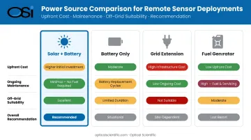
How Solar Compares to the Alternatives
| Power Source | Upfront Cost | Ongoing Maintenance | Off-Grid Suitability |
|---|---|---|---|
| Solar + battery | Moderate | Very low | Excellent |
| Battery only | Low | High (regular swaps) | Limited by capacity |
| Grid extension | Very high | Very low | Not viable at true remote sites |
| Fuel generator | Moderate | High (fuel, service) | Poor for unattended sites |
For deployments where site visits are infrequent and data continuity is non-negotiable, solar is the default choice. The upfront cost is real, but it eliminates the recurring failure modes — missed swaps, scheduling delays, data gaps — that battery-only systems accumulate over time.
Key Components of a Solar Power System for Remote IoT Sensors
Solar Panels
The photovoltaic panel is the primary energy source. For remote sensor nodes, monocrystalline panels are generally preferred — they offer higher efficiency per unit area, which matters when mounting space is constrained on a pole or enclosure.
Panel wattage depends on the sensor load and location; the sizing math is covered in the next section. For reference, NREL's PVWatts calculator and NASA POWER both provide free, location-specific solar irradiance data — use these tools rather than generic regional averages.
Charge Controllers: MPPT vs. PWM
The charge controller sits between the panel and the battery, preventing overcharge and managing energy flow. Two types dominate:
- PWM (Pulse Width Modulation): Connects the array directly to the battery, pulling panel voltage down to battery voltage. Simple and inexpensive, but wastes potential energy whenever panel voltage exceeds battery voltage significantly.
- MPPT (Maximum Power Point Tracking): Operates as a DC-to-DC converter, continuously adjusting the electrical operating point to extract maximum available power from the panel.
According to Victron, PV output changes approximately 4.5% per 10°C — meaning a cold morning at a mountain deployment site can meaningfully increase available panel voltage. MPPT captures that extra energy; PWM doesn't. For fixed remote installations with non-ideal orientation, partial shading, or temperature extremes, MPPT is the better choice.
Battery Chemistry Selection
Battery selection depends on deployment conditions. The three most common chemistries:
| Chemistry | Temp Range | Depth of Discharge | Cycle Life | Best For |
|---|---|---|---|---|
| Sealed Lead-Acid (AGM) | Moderate | ~50% | 300–500 cycles | Proven, low-cost; used by USGS and EarthScope polar programs |
| LiFePO4 | Better cold tolerance than standard Li-ion | ~80–90% | 2,000+ cycles | Remote sites needing high cycle life and deep discharge |
| Standard Li-ion (NMC) | Poor cold performance | ~80% | 500–1,000 cycles | Milder climates only |
Cold-weather deployments require particular attention: lithium chemistries lose meaningful capacity below freezing, and standard NMC cells can fail to charge safely at sub-zero temperatures. EarthScope's polar programs have documented success with sealed AGM batteries in harsh environments. LiFePO4 is generally the better lithium option for cold climates.
Supercapacitors
Supercapacitors aren't a replacement for batteries in multi-day autonomy designs. Their value is as a burst-current buffer — smoothing the high peak currents during radio transmissions. The Iridium 9603 satellite module, for example, peaks at 1.3A during transmit but averages far less. A supercapacitor absorbs that burst without straining the battery.
Power Management ICs
A PMIC handles voltage regulation (stepping 12V down to 3.3V for sensor MCUs), low-battery cutoff, and overcharge/over-discharge protection. In unattended deployments, these protection functions are not optional. A single over-discharge event can permanently reduce battery capacity.
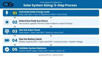
How to Size Your Solar Power System for Remote Sensors
Step 1 — Calculate Daily Energy Load
Map out every power state the sensor node operates in, then calculate daily consumption:
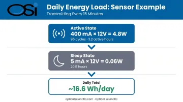
Example: sensor transmitting every 15 minutes
- Active sampling + transmit: 400 mA × 12V = 4.8W for 2 minutes per cycle
- 96 cycles/day × 2 min = 192 min active = 3.2 hours
- Sleep current: ~5 mA × 12V = 0.06W for 20.8 hours
- Daily load ≈ (4.8 × 3.2) + (0.06 × 20.8) ≈ 15.4 + 1.2 = ~16.6 Wh/day
OSI's OWI-series and APG-815-DS sensors draw a maximum of 400 mA at 12 VDC — a clean input for this type of calculation.
Step 2 — Determine Peak Sun Hours
Peak Sun Hours (PSH) represent the equivalent hours per day of full 1,000 W/m² solar irradiance for a given location. A location with 4 PSH receives the same daily energy as 4 hours of peak sun.
Critical rule: always use worst-case winter PSH, not annual averages. A site in Wyoming might average 5.5 PSH annually but see only 3.0 PSH in December. Size for December. Use NREL PVWatts or NASA POWER with your actual coordinates.
Step 3 — Size the Solar Panel
Formula:
Required panel wattage = (Daily Wh load ÷ PSH) × system loss factor
NREL's PVWatts Version 5 uses a default total system loss of 14% (factor of ~1.16). For remote sensor deployments, apply additional margin for winter irradiance reduction, battery aging, snow cover, and radio transmit bursts — a practical working range is 1.25–1.35 for conservative field designs.
Example from Step 1:
(16.6 Wh ÷ 3.0 PSH) × 1.3 = 7.2W panel minimum
A 10W panel provides sufficient design margin — roughly 39% above minimum.
Step 4 — Size the Battery Bank
Battery capacity must cover consecutive days without meaningful sun — called autonomy days.
Formula:
Battery Ah = (Daily Wh × Autonomy days) ÷ (System voltage × Allowable depth of discharge)
For temperate climates, 3–5 autonomy days is the standard target. Using the same example:
(16.6 Wh × 4 days) ÷ (12V × 0.8 DoD) = 6.9 Ah minimum
A 10–12 Ah LiFePO4 battery provides the working margin needed in the field.
Step 5 — Validate System Balance
With panel and battery sizes in hand, the final step is reconciling both against each other. Panel-battery mismatches cause real failures — overcharge damage from an oversized panel, or chronic energy deficits from an undersized one. Verify the design against these checks:
- Can the battery absorb a full day's panel output without reaching 100% state of charge too early?
- Does the system have enough stored energy to survive the worst-case consecutive cloudy days for the deployment location?
- Does your loss factor account for panel soiling, temperature derating, and wire losses separately?
Run the numbers for both summer peak production and winter minimum insolation. A design that only passes the summer case isn't ready for field deployment.
Low-Power Design and Communication Strategies for Solar-Powered Sensors
Minimizing Sensor Power Consumption
Three design choices have the greatest impact on power consumption in remote sensor deployments:
- Duty cycling: An MCU sleeping at microamp-level draw and waking only to sample and transmit cuts average load dramatically. A sensor sampling every minute instead of every 15 minutes requires roughly 15× more energy for the active-mode portion of its duty cycle.
- Intelligent hardware: OSI's OWI-650 LP-WIVIS powers up for one minute to report present weather and visibility, then shuts down automatically. Its Adaptive Heater Technology only activates lens heaters when dew or frost is detected. That kind of sensor-level power management directly reduces battery and panel sizing requirements.
- Built-in self-diagnostics: OSI sensors run continuous self-tests updating every minute, providing remote fault indication without requiring a site visit. This eliminates elevated power draw going undetected for weeks — a real risk on unattended deployments.
Choosing the Right Wireless Protocol
Protocol selection is a major energy decision. Transmit current often dominates the active-mode energy budget:
| Protocol | Range | Approx. Transmit Current | Infrastructure Needed | Best Use Case |
|---|---|---|---|---|
| LoRaWAN | Up to 30 miles (rural) | Very low (~20–40 mA typical) | Private or shared gateways | Remote environmental monitoring, default choice |
| NB-IoT | Cellular coverage area | Up to 395 mA (connected mode) | Cellular operator network | Sites with confirmed cellular coverage |
| LTE-M | Cellular coverage area | Up to 395 mA (connected mode) | Cellular operator network | Higher-data or mobile applications |
| Satellite (Iridium) | Global | 145 mA avg / 1.3A peak | None | Most isolated deployments; larger power budget required |
LoRaWAN is the practical default for remote environmental monitoring. It runs over unlicensed spectrum, supports private gateway deployments, and its ~20–40 mA transmit current fits comfortably within a solar-sized energy budget.
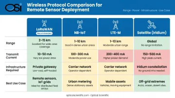
For sites beyond cellular coverage and too remote for a gateway, Iridium-based satellite communication is the fallback — but it requires careful attention to the 1.3A transmit peak when sizing batteries and supercapacitor buffers.
Real-World Applications: Solar-Powered Sensors in Environmental and Industrial Monitoring
Weather and Atmospheric Monitoring
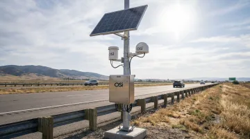
Road Weather Information Systems (RWIS) are among the most widespread solar-compatible sensor network deployments in operation. FHWA defines RWIS stations as Environmental Sensor Stations measuring atmospheric, pavement, and water-level conditions. Many sit at highway segments with no grid access. Ohio DOT expanded to 158 RWIS weather stations covering all 88 counties at a cost of approximately $3.7 million — running grid connections to each site would have made that scale impossible.
OSI's OWI and DSP-WIVIS sensor lines serve those same DOT networks across Maryland, Wyoming, Vermont, New Hampshire, Wisconsin, and Ohio. Their solar compatibility is straightforward by design:
- 12 VDC / 400 mA power draw integrates directly with standard 12V solar-charged battery systems (no conversion required)
- LP-WIVIS was engineered specifically for battery and solar deployment, with intermittent-mode operation that extends autonomy at low-sun sites
- Both lines are actively deployed across state highway networks where maintenance access is infrequent
Environmental and Emissions Compliance Monitoring
EPA 40 CFR Part 75 requires continuous monitoring and reporting of CO₂, NOx, and SO₂ emissions at regulated facilities. At outlying monitoring points such as flare stacks, terminal loading facilities, and remote pipeline infrastructure, solar power eliminates the need to run grid connections to each location.
OSI's OFS-2000 Optical Flow Sensor carries the same 12 VDC / 400 mA solar-compatible specification and is documented for deployment at thermal oxidizers, flare stacks, catalytic crackers, and terminal loading facilities. Its no-drift, no-field-calibration design is particularly suited to remote installations where a calibration technician visit is expensive.
Agricultural and Hydrological Monitoring
The NRCS SNOTEL network spans approximately 600 remote sites across the western US and Alaska, measuring snowpack and related climatic data entirely on solar power. USGS streamgages deliver river-height and streamflow data at 15-minute intervals, with solar panels trickle-charging 12V batteries at stations throughout the national network.
OSI's APG-815-DS and ORG-815-DS precipitation sensors are explicitly designed for these deployments — solar-compatible, no moving parts, no antifreeze chemicals, and capable of operating on unstable platforms including data buoys. Both have been deployed across every continent, including Antarctica.
Overcoming Common Challenges in Solar-Powered Remote Sensor Deployments
Soiling, Shading, and Panel Degradation
Dust, bird droppings, snow accumulation, and partial shading are the most common causes of underperformance in field-deployed solar systems. NREL's PVWatts applies a 2% default soiling loss to system estimates, but real-world soiling in agricultural or industrial environments can exceed that significantly.
Practical mitigations:
- Select panel tilt angles that encourage rain-based self-cleaning (steeper tilts shed debris more readily)
- Design inspection schedules around the deployment environment, not a fixed calendar
- Use MPPT controllers — they extract maximum power even from partially shaded or soiled panels by continuously optimizing the operating point
Extreme Temperature Impacts
Both high and low temperatures reduce system performance. The PV temperature effect runs approximately 0.45% per °C — a panel rated at 10W at 25°C produces meaningfully less on a hot summer afternoon and somewhat more on a cold, clear winter morning.
Battery performance is the more critical concern. Standard lithium-ion (NMC) cells lose significant capacity below freezing and cannot be safely charged at sub-zero temperatures without protection circuitry. For polar, mountainous, or high-altitude deployments:
- LiFePO4 chemistry handles cold better than NMC
- Insulated battery enclosures reduce temperature swings
- Panel sizing must account for reduced winter sun hours — the two cold-weather effects compound each other
OSI sensors operate across −50°C to 60°C, and their all-digital DSP-based design eliminates temperature-sensitive analog components. The Australian Antarctic Division operates OSI equipment in one of the harshest thermal environments on earth — which confirms that the sensing hardware typically isn't the limiting factor in cold-weather deployments. Battery selection is where most system designers need to focus their attention.
System Monitoring and Remote Diagnostics
Soiling, temperature swings, and seasonal irradiance shifts all degrade system performance gradually — which is exactly why remote visibility into energy health is as important as the sensor data itself. Battery voltage, state of charge, panel output, and charge controller status should be telemetered alongside measurement data so operators can detect energy problems before they cause downtime.
OSI sensors run continuous self-tests updating once per minute, with diagnostic outputs available over RS-232, RS-485, Ethernet, or cellular modem interfaces. Fault conditions are reported directly in the output message stream, including events like dew on lenses triggering heater activation. When energy system status and sensor health arrive in the same data feed, operators can triage problems remotely — distinguishing a low-battery alert from a sensor fault before committing to a site visit.
Frequently Asked Questions
How long can a solar-powered IoT sensor run without sunlight?
Autonomy depends on battery bank size and daily load. Properly sized systems typically deliver 3–7 days without sun. The key design variable is sizing the battery bank for worst-case consecutive overcast days at the deployment location, not average conditions.
What is MPPT and why does it matter for remote sensor power systems?
MPPT (Maximum Power Point Tracking) is a charge controller algorithm that continuously adjusts a panel's electrical operating point to extract maximum available power. It's especially valuable under partial shading, cold temperatures, or voltage mismatches between panel and battery — all conditions common in remote field deployments.
How do I calculate what size solar panel I need for a remote IoT sensor?
Divide daily energy consumption (Wh) by Peak Sun Hours for your location, then multiply by a system loss factor (NREL's PVWatts default is 14% losses). Always use worst-case winter PSH for the deployment coordinates, not the annual average.
Which wireless protocol is most energy-efficient for solar-powered remote sensors?
LoRaWAN is widely preferred for its long range (up to 30 miles in rural areas) and low transmit current. NB-IoT and LTE-M work where cellular coverage is confirmed. For truly off-grid locations, satellite (Iridium) is viable but its 1.3A peak transmit current requires careful battery sizing.
Can solar-powered IoT sensors operate in cold or extreme climates?
Yes, with the right components. LiFePO4 batteries outperform standard NMC lithium-ion in cold, and insulated enclosures are essential below freezing. Panel sizing must also account for reduced winter sun hours at high latitudes. OSI sensors are rated to −50°C and use all-digital designs that don't drift with temperature.
How much maintenance do solar-powered remote sensor systems typically require?
Maintenance requirements are minimal — typically panel cleaning as needed and a battery inspection or replacement every several years. OSI sensors carry an MTBF exceeding 80,000 hours and typically require field calibration only every two years, with built-in self-diagnostics that flag issues remotely before they cause downtime.