Introduction
Measuring particles accurately — whether in fog rolling across an airport runway, smoke pouring from an industrial stack, or aerosols circulating through a cleanroom — is harder than it sounds. Concentrations shift in seconds, environmental conditions vary wildly, and many settings make physical sampling impractical or impossible.
Forward light scattering photometry emerged from this need and has become the backbone of particle measurement across dozens of demanding applications. By detecting how particles deflect light at small angles relative to an incident beam, these instruments extract real-time data on concentration, extinction, and in some configurations, size — without touching the sample.
This article covers:
- What forward scattering photometry is and how it works
- The Mie scattering physics behind the measurement
- How photometers are designed around that physics
- How this method compares to alternatives
- Real-world applications — from FAA-certified runway visual range systems to EPA-regulated stack emissions monitoring
Key Takeaways
- Forward scatter photometry measures light deflected at small forward angles by particles to infer concentration or extinction
- Mie scattering theory (established 1908) explains why forward angles produce the strongest signal for particles in the ~0.1–5 µm range
- WMO guidance defines meteorological forward-scatter meters as using beam intersection angles of 20–50°
- MOR (Meteorological Optical Range) is derived from the measured extinction coefficient via the Koschmieder formula
- Airport RVR systems, cleanroom filter integrity testing, industrial PM CEMS, and road weather monitoring are the primary application areas
- No moving parts and built-in contamination monitoring suit these sensors for continuous outdoor and industrial deployment
What Is Forward Light Scattering Photometry?
Forward light scattering photometry is an optical measurement technique that quantifies particle concentration or atmospheric extinction by detecting light scattered at small angles relative to an incident beam.
A light source illuminates a sample volume; particles in that volume deflect some of that light forward, and a photodetector captures the scattered signal and converts it to a measurable electrical output.
A few distinctions matter here:
- Photometry vs. spectrometry: Photometry measures total light intensity — not spectral detail. It records how much light reaches the detector and at what signal level. That simplicity is a feature, not a limitation, for continuous particle monitoring.
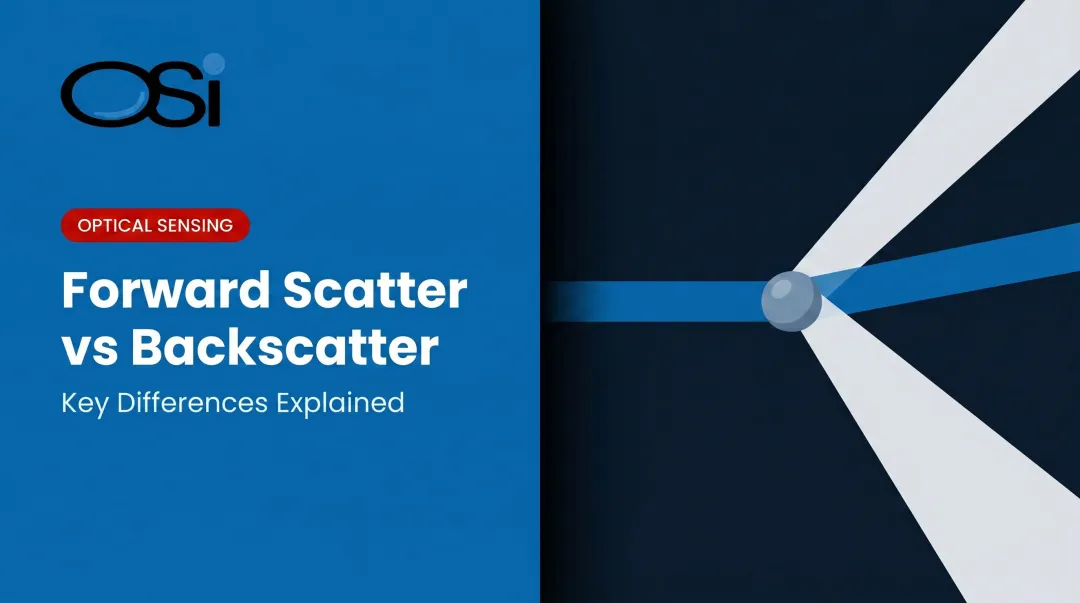
- Forward angle specificity: "Forward" means small angular offsets from the incident beam — not 90° side scatter or 180° backscatter. This angular region produces the strongest scattering signal for particles comparable in size to the light's wavelength.
- Measured outputs: Depending on instrument design, forward scatter photometers can report volume scattering coefficient, mass concentration, or meteorological optical range (MOR). Full particle size distributions require multi-angle collection or additional processing — they're not an inherent output of single-angle forward scatter designs.
The theoretical foundation is Mie scattering theory, published by Gustav Mie in 1908 in Annalen der Physik. Practical instruments built on this physics emerged from the 1960s onward — first in atmospheric research, then in industrial and regulatory monitoring as agencies like the EPA began requiring continuous emissions and visibility data.
The Physics Behind Forward Light Scattering: Mie Theory
Why Forward Angles Dominate
When a particle's diameter is comparable to or larger than the wavelength of incident light, it doesn't scatter uniformly in all directions. Instead, it produces a complex, angle-dependent pattern described by Mie theory. The key feature: the forward lobe dominates. Particles scatter disproportionately more light in the forward direction than at the side or back.
For visible light around 0.5 µm wavelength, Mie-regime behavior applies to particles roughly in the 0.05–5 µm diameter range. This is precisely the size range that matters most for atmospheric aerosols, filter challenge particles, and industrial particulates.
Size Dependence and Practical Limits
Scattering intensity at forward angles scales strongly with particle size:
- Larger particles scatter more light forward , which is useful for detecting higher mass concentrations
- Very small particles (well below wavelength, the Rayleigh regime) scatter more isotropically, reducing the forward-angle advantage
- Very large particles (rain droplets, coarse dust) produce geometric diffraction effects that still favor forward angles
This makes forward scattering most effective for particles in roughly the 0.1–5 µm range for visible light sources. ISO 14644-3 aerosol photometer examples, for instance, specify response for 0.1–0.6 µm particles at mass concentrations of 0.001 to 100 µg/L.
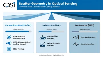
Comparing Scatter Geometries
| Geometry | Signal Strength | Best Application |
|---|---|---|
| Forward (20–50°) | Strongest | Concentration, MOR, filter testing |
| Side scatter (90°) | Moderate | Particle composition, internal structure |
| Backscatter (180°) | Weakest | Lidar, remote sensing |
Side scatter is more sensitive to particle composition and refractive index variations. Backscatter is used in lidar systems where the detector must be co-located with the source. Forward scatter wins on signal strength for most photometric concentration and visibility applications.
Wavelength and Refractive Index
Wavelength selection matters. Shorter wavelengths improve sensitivity to smaller particles; near-infrared wavelengths (the Vaisala FS11, for example, uses 875 nm) reduce interference from ambient sunlight in outdoor installations.
The complex refractive index of particles (real part governing refraction, imaginary part governing absorption) affects both the magnitude and angular shape of the forward scatter signal. Calibrating against reference particles of known composition is therefore essential when measuring aerosols of different types.
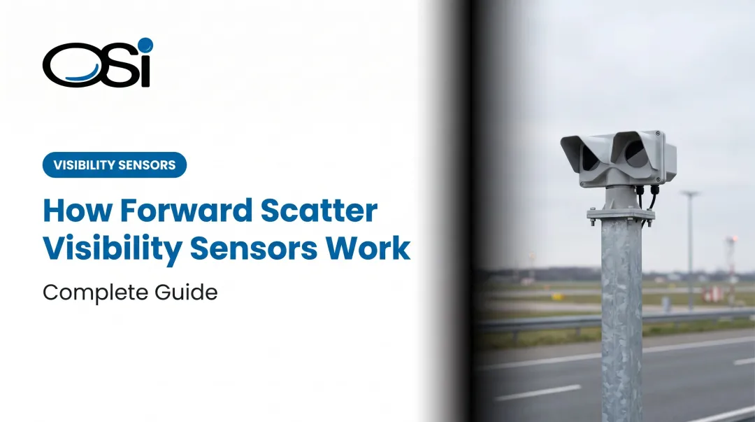
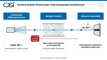
How a Forward Light Scattering Photometer Works
Core Optical Architecture
A forward scatter photometer has three essential components:
- A collimated LED or laser diode (typically near-IR) directed through a defined sample volume
- A sample volume consisting of either an open-path atmosphere or an enclosed flow-through cell
- A detector assembly positioned at a forward angle, typically behind a spatial filter (beam stop or obscuration bar) that blocks direct transmission and captures only scattered light
Per WMO guidance, meteorological forward-scatter meters position their transmitter and receiver beams to intersect at 20–50°, sampling a small defined air volume with installations typically requiring just 1–2 meters of physical space.
Signal Processing
The photodetector converts scattered photons to a current or voltage signal, which is amplified and digitally processed. Signal magnitude correlates to particle or aerosol concentration; in photometric mode, the output is an ensemble measurement across all particles in the sample volume simultaneously — not individual particle counts.
Open-Path vs. Enclosed Cell Configurations
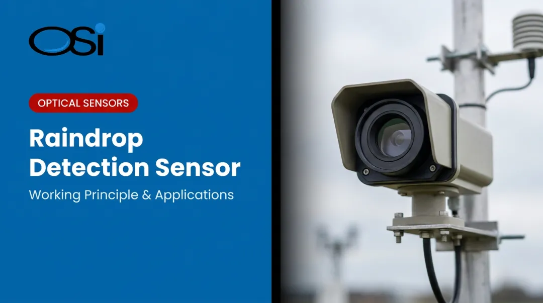
- Open-path: Used for atmospheric visibility measurement (airports, highways, maritime). The measurement volume is a sample of the ambient air between transmitter and receiver.
- Enclosed flow-through cells: Used for filter integrity testing, liquid particle analysis, and stack gas monitoring. The sample is drawn or forced through a defined chamber.
Each geometry affects collection solid angle, sensitivity, and dynamic range. These tradeoffs directly shape calibration requirements for each deployment type.
Calibration
For atmospheric applications, WMO specifies that forward-scatter meters used for RVR should have calibration traceable to transmissometer standards over the full operating range. OSI's OWI-series sensors take a different approach: their all-digital DSP-based architecture with AI-derived algorithms eliminates the need for periodic field calibration by design. OSI's OFS-series measurement algorithm is also independently certified by NIST.
Forward Scattering vs. Other Optical Detection Methods
Each optical particle method occupies a distinct niche. Understanding the differences helps engineers select the right tool.
Forward Scatter vs. Nephelometry
Nephelometers integrate scatter across a wide angular range to characterize total scattering coefficient — useful for turbidity and broad atmospheric extinction studies. Forward-scatter photometers collect signal at a specific forward angle instead, which delivers:
- Higher sensitivity for defined particle size ranges
- Better performance in directional beam configurations
- More reliable MOR and RVR measurements in field deployments
Forward Scatter vs. Laser Diffraction
ISO 13320:2009 laser diffraction covers particle sizing from approximately 0.1 µm to 3 mm by collecting scatter across many angles simultaneously to reconstruct a full size distribution. Forward scatter photometry at a fixed angle trades that size-distribution detail for simpler optics, faster response, and lower cost. That tradeoff makes it better suited for real-time continuous field monitoring than for detailed laboratory characterization.
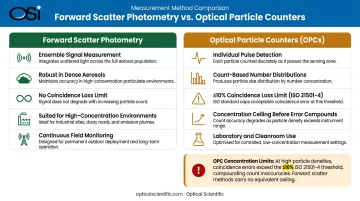
Forward Scatter vs. Optical Particle Counters (OPCs)
OPCs detect individual particle pulses, generating count-based number distributions. Per ISO 21501-4 guidance, coincidence loss at maximum measurable concentration must remain ≤10% — meaning OPCs face hard concentration limits before errors compound.
Forward-scatter photometers measure ensemble signals instead, so they remain robust in dense aerosols and high-concentration industrial environments where OPCs saturate.
Key Applications of Forward Light Scattering Photometry
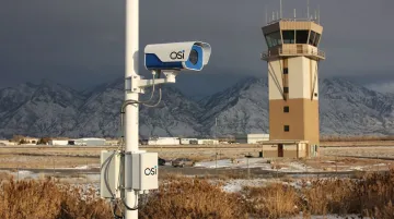
Atmospheric Visibility and Airport RVR
This is the strongest and best-documented application for forward-scatter photometry. The instrument measures the volume scattering coefficient of the air in the sample volume; MOR is then derived using the Koschmieder relationship: MOR = −ln(0.05)/σ, where σ is the extinction coefficient (per WMO No. 8).
FAA specification FAA-E-2772B explicitly identifies the RVR visibility sensor as a forward-scatter meter and designates forward-scatter technology as the preferred approach for NAS RVR visibility sensing. WMO confirms forward-scatter meters are capable of measuring RVR across MOR ranges from roughly 10 m to 50+ km.
OSI's OWI-series sensors — including the OWI-430 DSP-WIVIS and OWI-650 LP-WIVIS — use off-axis forward scattering as one of three detection technologies in a triple-aperture optical system. These sensors are deployed across FAA AWOS installations, NOAA NWS ASOS networks, and state DOT RWIS systems in Maryland, Ohio, Wyoming, Vermont, Wisconsin, and New Hampshire, among others.
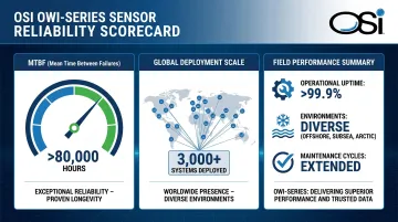
With over 3,000 systems fielded globally and algorithms built from over 800 million field hours of operational data, the OWI platform represents one of the most extensively deployed forward-scatter visibility systems in service.
Filter Integrity Testing (HEPA/ULPA)
ISO 14644-3 defines aerosol photometer use for installed filter leakage testing in cleanrooms. An upstream challenge aerosol is generated; a downstream photometer scans for any particles penetrating the filter. The standard describes forward-scattered-light optical chambers with detection capability starting at penetration levels of 0.01% of upstream aerosol concentration, covering mass concentrations from 0.001 to 100 µg/L for particles in the 0.1–0.6 µm range.
This method provides real-time, spatially localized leak detection that batch sampling cannot match. Critical deployment environments include:
- Pharmaceutical manufacturing cleanrooms requiring continuous contamination control
- Semiconductor fabrication facilities with sub-micron particle sensitivity requirements
- Hospital isolation units where filter integrity directly affects patient safety
Stack Emissions and Industrial Particulate Monitoring
EPA Performance Specification 11 (PS-11, updated January 2019) covers PM continuous emission monitoring systems (CEMS) at stationary sources. Optical methods play a central role in PM CEMS because they enable in-situ, real-time measurement without extracting or conditioning the sample gas.
For facilities requiring full EPA 40 CFR Part 75 compliance, stack measurement systems typically combine optical PM monitoring with complementary flow measurement. OSI's OFS-2000 series addresses the flow side of that equation using optical scintillation to measure stack gas velocity across the full cross-section without contact — a different operating principle than forward-scatter photometry, but often deployed alongside PM CEMS in the same compliance package. OFS-2000 systems have been fielded at facilities operated by Duke Energy, Dominion Virginia Power, and other major power generators.
Research and Atmospheric Science
Forward scatter instruments remain standard tools in aerosol science, combustion studies, and climate research. Applications include characterizing particle size distributions in laboratory-generated aerosols, measuring aerosol optical depth in field campaigns, and validating satellite-based atmospheric retrievals with ground-truth optical data.
Why Forward Light Scattering Suits Demanding Environments
Signal Strength Advantage
The forward lobe of the Mie scattering pattern is substantially stronger than side or back scatter. This translates directly to better signal-to-noise ratios, the ability to detect lower particle concentrations, and the option to use lower-powered (less expensive, longer-lived) light sources without sacrificing measurement quality.
Ruggedness for Continuous Outdoor Deployment
Modern forward-scatter photometers are designed for unattended operation:
- Solid-state electronics and static optics eliminate mechanical wear with no moving parts
- Automatic window contamination monitoring detects dew, frost, and dirt accumulation, reporting status continuously — OSI's OWI sensors include this as standard
- Weatherproof enclosures handle temperature extremes, high winds, and direct precipitation
That reliability extends to the hardware itself. OSI's OWI-series sensors carry an MTBF exceeding 80,000 hours, with field deployments routinely exceeding that figure. WMO further notes that forward-scatter meters show lower susceptibility to pollution than transmissometers — a meaningful advantage in roadside, maritime, and industrial sites where airborne contaminants are constant.
Real-Time Continuous Monitoring
Durability only matters if the instrument is also delivering data when it counts. Forward-scatter photometers produce stable, averaged signals at high update rates — OSI's OWI sensors provide instantaneous readings every 10 seconds with standard one-minute reporting. For safety-critical applications — runway closures triggered by sudden fog, filter breach alarms in pharmaceutical filling lines, exceedance alerts at power plant stacks — that response time directly determines whether operators can act before conditions become dangerous.
Frequently Asked Questions
What is the difference between forward light scattering and backscattering in photometry?
Forward scattering occurs at small angles near the incident beam and produces stronger signals because the Mie scattering forward lobe dominates. Backscattering (180°) captures light returning toward the source; the signal is weaker, but this geometry suits lidar and remote sensing where placing a detector on the far side of the measurement volume is impractical.
What wavelength of light is typically used in forward light scattering photometers?
Wavelengths commonly range from visible to near-infrared. The Vaisala FS11, for example, operates at 875 nm; other instruments use similar near-IR wavelengths. Near-IR reduces ambient light interference in outdoor applications, while shorter visible wavelengths improve sensitivity to sub-micron particles. OSI's OWI series uses an infrared LED source, though specific nanometer wavelength is available from OSI's technical team.
How does a forward light scattering sensor measure visibility or meteorological optical range?
The sensor measures the volume scattering coefficient (σ) of the air sample. MOR is then derived using the Koschmieder relationship defined in WMO No. 8: MOR = −ln(0.05)/σ — the distance at which a black object becomes indistinguishable from the horizon sky at a contrast threshold of 0.05.
What types of particles can forward light scattering photometry detect?
The method detects a broad range of aerosols — fog and rain droplets, dust, smoke, industrial particulate matter, and filter challenge aerosols. Effective detection ranges vary by instrument: ISO 14644-3 aerosol photometer examples cover 0.1–0.6 µm particles, while larger configurations can address coarser particles. No single size range applies universally across all forward-scatter instrument classes.
Can forward light scattering photometers operate reliably in harsh outdoor or industrial environments?
Yes. Modern instruments use weatherproof enclosures, solid-state designs with no moving parts, and built-in contamination monitoring that alerts operators before data quality degrades. OSI's OWI-series sensors report an MTBF exceeding 80,000 hours, with field performance noted to exceed that benchmark — and they've been validated across deployments from Antarctica to tropical environments.
How does forward light scattering photometry differ from laser diffraction particle sizing?
Laser diffraction collects scatter across many angles simultaneously to reconstruct a full particle size distribution (0.1 µm to 3 mm per ISO 13320). Forward scatter photometry at a fixed angle measures ensemble intensity: simpler optics, faster response, lower cost, but no full size distribution. The first suits detailed lab characterization; the second is built for real-time continuous field monitoring.