NOAA's National Weather Service operates around 950 ASOS stations across the United States, virtually all using forward scatter as the automated visibility measurement method. The technology is that embedded. And yet the optical mechanics — why a 42°–45° scatter angle, what the Koschmieder equation actually means, how a sensor distinguishes fog from a dirty lens — rarely appear outside academic papers.
This guide covers all of it. From light emission to MOR output, in practical language.
Key Takeaways
- Forward scatter sensors emit a light beam into a defined air volume and measure how much scatters off airborne particles at a forward angle
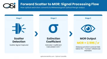
- Scatter intensity converts to an extinction coefficient (σ) and then to Meteorological Optical Range using MOR = 2.996 / σ
- Engineered at 42°–45°, the scatter geometry captures broad particle-size sensitivity without direct-beam interference
- No scheduled maintenance required — sensors operate unattended 24/7 and integrate directly into AWOS, RWIS, and maritime systems
- Unlike transmissometers, forward scatter sensors work in a single compact unit — no 75–300 meter baseline required
What Is a Forward Scatter Visibility Sensor?
A forward scatter visibility sensor is an electro-optical instrument that quantifies atmospheric visibility by measuring the intensity of light scattered forward by airborne particulates — water droplets, aerosols, dust, smoke — suspended within a defined sampling volume of open air.
The Problem It Was Designed to Solve
Traditional human visibility observation is subjective and unavailable at unmanned stations. Transmissometers, the earlier automated alternative, required a transmitter and receiver separated by 75–300 meters, which is impractical for many real-world installations. Forward scatter sensors solved this with a self-contained, single-station design that fits on a standard mounting pipe with no cement pad required.
Unlike transmissometers, a forward scatter sensor does not measure visibility along an extended optical path. It infers visibility from a small, localized sampling volume. Siting matters for this reason: a sensor mounted next to a building, reflective surface, or heat exhaust vent will not represent the surrounding atmosphere accurately.
Why These Sensors Dominate Automated Networks
Forward scatter sensors are the standard technology behind AWOS and ASOS visibility reporting globally because they combine three qualities no other approach matches simultaneously:
- Single-unit installation with no baseline infrastructure required
- No moving parts, enabling continuous unattended operation with self-monitoring electronics
- Compatible across airports, highways, maritime ports, and remote research stations
OSI's OWI-430 DSP-WIVIS, for example, incorporates forward scatter visibility measurement alongside present weather detection in a triple aperture optical system, covering both functions without separate instruments.
How Does a Forward Scatter Visibility Sensor Work?
The measurement cycle is continuous and automatic: a light source emits into the atmosphere, particles scatter a fraction of that light at a forward angle, a detector captures the scattered energy, and a processor converts that signal into a visibility reading. The entire cycle completes within seconds.
Initiation: Light Emission
The transmitter fires a light source — in ASOS-deployed sensors, a pulsed Xenon flash lamp; in OSI's OWI series, an infrared LED — into a defined sampling volume of open air. According to NOAA's National Weather Service, ASOS visibility sensors transmit light twice per second into a sampling volume of approximately 0.75 cubic feet.
The transmitter and receiver are not aligned. They are deliberately offset — typically at 42°–45° — so the detector only receives light that has been scattered by the intervening atmosphere. Direct beam illumination never reaches the detector.
Core Operation: Scatter Detection and the Extinction Coefficient
When the light beam encounters airborne particles, a fraction deflects forward at angles close to the original beam direction. This is forward scattering. Its intensity scales with particle concentration — denser fog means more scatter, more signal.
A photodiode receiver measures the power of scattered light arriving from the sampling volume. The processor then converts this signal into an extinction coefficient (σ), expressed in inverse kilometers. The extinction coefficient represents how rapidly light attenuates as it travels through the atmosphere: a high σ value indicates a dense atmosphere and reduced visibility.
From σ, the processor calculates Meteorological Optical Range using the Koschmieder equation:
MOR (km) = 2.996 / σ
The constant 2.996 comes from the threshold contrast of the human eye. MOR is defined as the distance at which a black object against the horizon drops below 5% contrast visibility — meaning it's human-referenced, not arbitrary. This is why MOR is the international standard for atmospheric visibility reporting under WMO and ICAO guidelines.
OSI's sensors report the atmospheric extinction coefficient directly alongside visibility — a requirement for runway visual range (RVR) algorithm inputs at aviation installations. That combination of outputs sets up the sensor's next function: monitoring its own measurement integrity.
Regulation and Self-Monitoring
The processor doesn't just calculate visibility — it continuously watches itself. In OSI's OWI series, self-diagnostics update every minute and include:
- Flags dew, frost, or persistent fouling with a "CL" code when lens cleaning is required
- Compensates automatically for partial lens obscuration from dust, water droplets, or ice without interrupting measurement
- Eliminates signal drift using all-digital DSP with no temperature-sensitive analog components — stable from -50°C to 60°C
- Corrects for ambient light using an integrated sensor that shares the same optics and field of view as the scatter receiver
Dual self-regulating lens heaters run continuously, drawing more current in cold conditions and less in warm ones — preventing ice and condensation without traditional thermostatic cycling.
Output: Visibility Reporting
The processor averages multiple scatter samples — OSI's sensors output a full data update every 60 seconds with instantaneous intensity updates every 10 seconds — and reports MOR in the format required by the receiving system: statute miles for METAR aviation reports, kilometers for road weather and maritime applications.
Output feeds directly into:
- AWOS/ASOS automated weather observation platforms
- Road Weather Information Systems (RWIS)
- Port meteorological and vessel traffic networks
OSI's OWI series supports the following communication interfaces:
- RS-232 (standard)
- RS-485
- Ethernet
- MODBUS RTU
- Cellular modem
This range covers integration requirements across the most common data acquisition platforms in aviation, transportation, and industrial deployments.
Key Design Features That Ensure Reliable Performance
The 42°–45° Scatter Angle
This geometry is not arbitrary. At angles below roughly 20°, the signal becomes strongly dependent on particle size — fine aerosols and large raindrops produce very different responses, making calibration unreliable. At very high angles (backscatter), signal strength drops sharply.
The 42°–45° range is where the sensor detects meaningful scatter contributions from fine aerosols through large precipitation drops without strong angular dependence on particle size. That balance makes this range the de facto standard across meteorological forward scatter sensors — stable enough to calibrate reliably, sensitive enough to cover the full range of atmospheric particles.
Physical Protection Against Real-World Failure Modes
no moving parts and requires no scheduled maintenance. Three design characteristics support this:
- Dirt tolerance: The system is insensitive to gradual optic contamination — AI compensation handles partial obscuration automatically
- Thermal stability: All-digital DSP-based design eliminates temperature-sensitive analog components that degrade over time
- Proven longevity: MTBF exceeds 80,000 hours across OSI's sensor portfolio, with many field-deployed units running well beyond that mark
Where Forward Scatter Visibility Sensors Are Used
Primary Deployment Environments
Aviation — AWOS/ASOS: Forward scatter sensors feed visibility data into METAR reports used for instrument approach decisions. Accurate real-time visibility is a hard requirement for pilots executing instrument approaches, making sensor reliability non-negotiable.
Highway Road Weather (RWIS): RWIS installations on high-risk corridors use visibility sensor data to trigger variable message signs and lane closures. FHWA data shows fog causes over 38,700 crashes, 600+ fatalities, and 16,300+ injuries annually on U.S. roads — which is exactly why state DOTs in Maryland, Ohio, Wisconsin, Wyoming, Vermont, and New Hampshire rely on automated visibility monitoring from OSI sensors.
Maritime: Harbor entrance monitoring, vessel traffic services, and port approach systems use forward scatter sensors for real-time visibility alerts to vessel operators.
Secondary Industries
- Power plants and refineries — fog and particulate monitoring for worker safety and process control
- Military weather operations — OSI sensors serve the U.S. Army, Air Force, and Navy
- Remote research stations — including polar and high-altitude sites requiring unattended continuous operation (OSI sensors have operated in Antarctica)
- Industrial fence line monitoring — particulate and visibility conditions at facility perimeters
Across all of these environments, OSI's FAA-certified AWOS systems and visibility sensors are trusted by the FAA, NOAA National Weather Service, NASA, and EPA — agencies that require verified, continuous measurement accuracy in safety-critical conditions.
Forward Scatter Sensors vs. Transmissometers: Key Differences
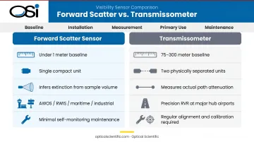
Transmissometers project a beam across a long baseline — typically 75–300 meters — between a physically separated transmitter and receiver, measuring actual optical path attenuation directly. That direct measurement is their core advantage.
| Forward Scatter Sensor | Transmissometer | |
|---|---|---|
| Baseline | < 1 meter (single unit) | 75–300 meters |
| Installation | Compact, no alignment required | Precise long-distance alignment |
| Measurement method | Infers extinction from sample volume | Measures actual path attenuation |
| Primary use | AWOS, RWIS, maritime, industrial | Precision RVR at major hub airports |
| Maintenance | Minimal, self-monitoring | Regular alignment and calibration checks |
Transmissometers remain the reference standard for Runway Visual Range (RVR) at major hub airports, and the accuracy difference is real. Per FAA Order 6560.10D, legacy transmissometer RVR systems are no longer being installed as new systems in the U.S. — newer scatter-effect systems using infrared technology have largely replaced them. Even so, transmissometers retain a precision edge in highly variable or patchy visibility conditions, where a small sample volume may not represent the full approach path.
Across most operational contexts — automated weather stations, RWIS, secondary airports, maritime ports, industrial monitoring — forward scatter sensors deliver equivalent accuracy without the alignment requirements, baseline footprint, or ongoing calibration overhead that transmissometers demand.
Frequently Asked Questions
How does a forward scatter visibility sensor work?
The sensor emits a pulsed infrared light beam into a defined air sampling volume. A detector offset at roughly 42°–45° captures only the light scattered forward by airborne particles — never direct beam light. A processor converts scatter intensity into an extinction coefficient, then calculates MOR using MOR = 2.996 / σ.
What is the CS125 present weather and visibility sensor?
The CS125 is a forward scatter sensor made by Campbell Scientific that measures visibility (MOR) and present weather type — rain, snow, fog, drizzle — from a single compact unit. OSI's OWI series sensors serve the same operational purpose using patented optical scintillation-based technology.
What is the difference between a forward scatter sensor and a transmissometer?
A transmissometer measures light attenuation directly across a 75–300 meter fixed path between two physically separated units. A forward scatter sensor infers visibility from scatter within a compact single-station sampling volume. Forward scatter sensors are simpler to install; transmissometers offer direct path measurement preferred for precision RVR at major hub airports.
What is Meteorological Optical Range (MOR) and how is it calculated?
MOR is the standard scientific measure of atmospheric visibility — the distance at which a black object against the horizon falls below a 5% contrast threshold relative to the background sky. It is calculated using the Koschmieder equation: MOR = 2.996 / σ, where σ is the extinction coefficient in inverse kilometers measured by the sensor.
How do forward scatter sensors perform in heavy rain or snow?
These sensors are designed for continuous operation through precipitation. Features like self-regulating lens heaters, automatic lens compensation algorithms, and no-hood optical designs prevent blockage and ice formation. OSI's OWI sensors can measure precipitation rates up to 1,000+ mm/hr across all precipitation types.
What industries use forward scatter visibility sensors?
Aviation (AWOS/ASOS at airports), road transportation (highway RWIS), maritime (port and harbor monitoring), industrial safety (refineries, power plants, chemical facilities), military weather operations, and remote atmospheric research.