MOR is the physics-defined, internationally standardized quantity at the core of every automated visibility system. It replaces subjective human observation with a sensor-measurable value that aviation, transportation, maritime, and environmental sectors can act on consistently. WMO guidance (WMO No. 8) and ICAO standards both treat MOR as the accepted baseline for automated visibility reporting.
Understanding what MOR actually measures — and what it doesn't — is essential for anyone specifying sensors, interpreting METARs, or making safety-critical operational calls. This guide covers the governing physics, real-world influencing factors, measurement technologies, sector-specific thresholds, and the most consequential misapplications practitioners encounter.
Key Takeaways
- MOR is the path length through which a collimated light beam attenuates to 5% of its initial value — an objective, physics-derived quantity, not a human visibility estimate
- MOR is governed by the atmospheric extinction coefficient; denser scatterers (fog, smoke, dust) produce lower MOR values
- Aviation, highway, and maritime sectors each apply different MOR-derived thresholds that are sector-specific and not interchangeable
- Two primary sensor technologies measure MOR: transmissometers (high accuracy, two-unit) and forward-scatter sensors (compact, widely deployed)
- The two most consequential MOR misapplications: equating it with human visual perception, and reacting only at threshold crossings
What MOR Represents in Atmospheric Visibility Measurement
The Formal Definition
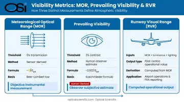
WMO No. 8, Chapter 9 defines MOR as the length of atmosphere over which the luminous flux of a collimated beam — standardized to a 2700 K incandescent lamp color temperature — is attenuated to 5% of its initial value, corresponding to a transmission factor of 0.05.
The governing physics come from the Beer-Lambert law of atmospheric extinction:
MOR ≈ 3 / σ_ext
where σ_ext is the volume extinction coefficient (m⁻¹), representing the combined scattering and absorption by atmospheric gases and particles. The constant 3 derives from −ln(0.05) ≈ 2.996, rounded in practice.
How MOR Differs from Visual Range
This 5% transmission threshold is not the same as human visual contrast perception. The Koschmieder visual range formula uses a 2% contrast threshold, yielding approximately 3.912 / σ_ext — about 1.31 times the MOR value for the same extinction coefficient. Under identical atmospheric conditions, MOR will therefore read consistently lower than Koschmieder visual range.
MOR is also distinct from two commonly confused terms:
- Prevailing visibility — a human observer's estimate based on identifying objects against contrasting backgrounds, governed by the ~2% contrast threshold rather than MOR's 5% transmission criterion
- Runway Visual Range (RVR) — the operationally computed distance a pilot on runway centerline can see markings or lights, incorporating background luminance and runway lighting intensity in addition to extinction; RVR is calculated from MOR but is not the same quantity
MOR's Role in the System
ICAO Annex 3 explicitly states that definition (a) of visibility — the greatest distance at which a dark object can be seen against a bright background — is represented by MOR. This alignment means that any automated visibility sensor used in METAR reporting or aerodrome observation must produce MOR-based output to satisfy international standards.
In practice, MOR serves three distinct roles within any observation system:
- A sensor design parameter (instruments must resolve the required MOR range for the application)
- An operational reporting metric (encoded in METARs and surface observations)
- A regulatory compliance threshold (triggering mandatory operational responses when crossed)
These roles are not interchangeable. A sensor that accurately reports MOR for METAR encoding may still lack the dynamic range needed for low-visibility runway operations — which is why matching instrument capability to application requirements matters from the outset.
Factors That Influence MOR in Real-World Conditions
Particle Type, Size, and Concentration
MOR is primarily driven by what's in the air — specifically the type, size, and concentration of atmospheric scatterers. Research by Zhang et al. found that over 81% of atmospheric extinction in studied conditions was attributable to particles in the 0.2–1.0 µm size range — the submicron regime where Mie scattering efficiency peaks relative to particle mass. This matters for sensor specification and for interpreting MOR data: PM mass alone is an incomplete predictor of extinction.
Different environments produce different scatterer profiles:
- Humid conditions — water droplets from fog, mist, drizzle, rain, or snow dominate
- Dry or polluted conditions — dust, smoke, industrial aerosols, and sea salt are primary drivers
- Mixed environments — hygroscopic growth of aerosol particles at elevated humidity creates complex, compounding effects
Humidity and Temperature Interactions
Humidity deserves particular attention. Wang et al. found that visibility enters a distinctly RH-sensitive regime above 75% relative humidity. At that threshold, hygroscopic aerosol growth accelerates — increasing σ_ext and reducing MOR even without any additional dry particle load or visible precipitation.
Two other variables compound this further:
- Temperature governs condensation onset, converting haze into fog with little warning
- Wind disperses or concentrates scatterers, creating spatial MOR gradients that a single point sensor cannot fully resolve
Atmospheric conditions can shift from benign to hazardous in minutes. Continuous, real-time automated MOR measurement captures those transitions; periodic human observation often cannot.
MOR Measurement Range and Operational Thresholds
Aviation-Specific Thresholds
Aviation uses RVR as its primary operational metric, with MOR as the underlying atmospheric input. Per ICAO Doc 9365, the ILS approach category minimums are:
| Category | Decision Height | RVR Minimum |
|---|---|---|
| CAT I | ≥ 60 m (200 ft) | ≥ 550 m |
| CAT II | < 60 m, ≥ 30 m | ≥ 300 m |
| CAT IIIA | < 30 m or none | ≥ 175 m |
| CAT IIIB | < 15 m or none | < 175 m, ≥ 50 m |
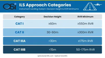
Note: FAA minimums differ from ICAO in specific breakpoints — for example, FAA CAT I typically requires RVR ≥ 2,400 ft (reducible to 1,800 ft with appropriate lighting). Always cite the controlling jurisdiction for operational documents.
FAA-certified Automated Weather Observing Systems (AWOS) are the designated instruments for generating MOR-derived visibility reports at certified aerodromes. FAA JO 6560.20C specifies visibility sensor optics mounted at 10 ±2 ft above ground. OSI's AWOS-AV system is one such certified solution, complying with FAR 91.171 and 91.175.
Highway Thresholds
Road visibility thresholds are local and program-specific. No universal MOR cutoff applies across state DOTs. Documented examples from FHWA case studies include:
- ALDOT (I-10): Speed reductions at visibility levels of 900 ft, 660 ft, 450 ft, and 280 ft — progressively lower limits as MOR drops
- WSDOT (I-90 Snoqualmie Pass): Speed reduced to 55 mph below 0.2 mi visibility, 45 mph below 0.1 mi
OSI's OWI-430 and OWI-650 visibility sensors are deployed in RWIS applications across multiple state DOTs, including Maryland, Ohio, Wisconsin, Wyoming, Vermont, and New Hampshire, providing real-time MOR data that feeds variable message signs and traffic management systems.
Maritime Applications
COLREGs Rule 3(l) defines "restricted visibility" by conditions (fog, mist, snow, heavy rain, sandstorms), not by a numeric MOR value. Rule 19 requires safe speed and appropriate lookout measures; Rule 35 governs sound signals. No COLREGS-mandated MOR threshold number exists. Maritime operators should tie procedures to the governing Rules and local port authority requirements rather than applying a universal MOR trigger.
OSI's OWI-650 sensors have been deployed in active maritime environments, including North Atlantic data buoys, where they monitor visibility, precipitation, and present weather under harsh conditions.
METAR Encoding
WMO No. 306 FM 15/16 specifies how MOR values are encoded in METAR reports, with resolution varying by visibility range:
- 50 m steps up to 800 m
- 100 m steps from 800–5,000 m
- 1,000 m steps from 5,000–9,999 m
- 9999 for visibility ≥ 10 km; CAVOK when additional cloud and weather conditions are met
Automatic stations transmit MOR continuously; METAR snapshots are typically at 30- or 60-minute intervals, with special observations issued when thresholds are crossed.
How MOR Is Measured, Reported, and Validated
Sensor Technologies
Two primary technologies measure MOR:
Transmissometers
- Project a collimated beam across a fixed baseline and directly measure transmission
- WMO No. 8 formula: MOR = x × ln(0.05) / ln(T), where x is baseline length
- High accuracy; serve as the calibration reference for other sensor types
- Require two-unit installation; ICAO Doc 9328 notes that forward-scatter meters require calibration traceability back to transmissometer fog measurement
Forward-scatter sensors
- Illuminate a small air volume with a pulsed source (infrared LED or similar)
- Measure light scattered at a forward angle to infer σ_ext and compute MOR
- Single-unit installation; more compact and widely deployed for road, maritime, and multi-purpose monitoring
- WMO No. 8 states achievable MOR measurement uncertainty is the larger of 20 m or 20%, depending on obscuration cause
OSI's OWI-430 DSP-WIVIS uses a proprietary triple-aperture optical system combining in-beam optical scintillation (for precipitation discrimination) and off-axis forward scattering (for MOR). The system also reports atmospheric extinction coefficient and ambient light levels required for RVR algorithm calculations.
Calibration and Self-Diagnostics
Calibration requirements under WMO and ICAO guidance apply to sensors used in official reporting, with traceability back to reference transmissometer measurements. Standards set no fixed universal calibration interval; requirements vary by application and jurisdiction.
OSI's DSP-based instruments address these requirements through built-in design features:
- Automatic Gain Control (AGC) compensates for dust, water droplets, and ice or snow on lenses
- Continuous built-in self-test reports sensor status and lens condition codes, including "CL" for cleaning needed and "ER" for error conditions
- No field calibration required — the all-digital, drift-free design eliminates temperature-sensitive analog components
- MTBF exceeding 80,000 hours, supported by a no-moving-parts design and over 800 million field hours of operational data
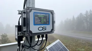
Traditional transmissometers require regular manual optics cleaning; OSI's design eliminates that scheduled burden entirely. That difference is especially practical for sensors deployed at remote or difficult-to-access sites, where unplanned technician calls are costly.
Point Measurement vs. Spatial Coverage
Even a well-calibrated sensor only measures MOR in the air volume immediately surrounding it. That local sample may not represent conditions across the full area being monitored — a distinction that deployment standards address directly.
ICAO Annex 3 and Doc 9328 address this directly for aviation: more demanding operations require RVR assessment at touchdown zone, mid-point, and stop-end positions, with sensors at approximately 2.5 m height and no more than 120 m lateral distance from runway centerline.
For road deployments, sensor spacing must reflect the length of the hazard zone and the spatial variability of fog events along a corridor.
Common Misinterpretations of MOR in Practice
Getting MOR data is only half the problem. Misapplying it is where safety exposure accumulates.
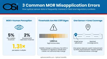
Conflating MOR with human-perceived visibility. Because MOR uses a 5% transmission threshold and human vision uses approximately a 2% contrast threshold, the Koschmieder visual range for any given atmospheric condition is approximately 1.31 times the MOR value. Operators who treat MOR readings as direct equivalents of what a pilot or driver perceives systematically underestimate actual perceived visibility. The relationship is consistent and calculable — so document the conversion basis when using it.
Treating WMO threshold categories as hard operational boundaries. Fog is typically classified as MOR below 1,000 m, mist from 1,000–2,000 m, and haze from 2,000–5,000 m. These are reporting categories, not cliff edges in physical conditions. Atmospheric extinction changes continuously — conditions at 999 m and 1,001 m are not dramatically different. Operational response plans should include margins above regulatory minimums rather than triggering only at threshold crossings.
Applying a single sensor's reading as representative of an extended area. A forward-scatter sensor samples a small air volume near the instrument. It cannot capture the spatial MOR gradient across a 3,000 m runway or a 5 km highway corridor. Sensor siting and network density must match the spatial scale of the hazard being monitored. A single well-calibrated sensor in the wrong location still produces data that misrepresents the risk zone.
Conclusion
MOR is a precisely defined atmospheric parameter with direct operational consequences across aviation, transportation, maritime, and environmental monitoring. It is objective and reproducible by design — but that objectivity only translates into safety when sensor technology, siting, calibration discipline, and threshold interpretation are all correct.
Sound application requires:
- Understanding the extinction physics behind the reported number
- Selecting sensor technology matched to the specific application
- Placing sensors where spatial gradients are operationally significant
- Maintaining calibration traceability to recognized standards
- Interpreting threshold crossings as points on a continuous scale, not binary switches
The difference between MOR and perceived visual range, between a point sample and an area representation, and between a reporting category and a hard physical boundary are not academic distinctions. These gaps appear in accident investigations and regulatory findings.
Frequently Asked Questions
What is the meteorological optical range (MOR)?
MOR is the WMO/ICAO-standardized path length over which a collimated 2700 K light beam attenuates to 5% of its initial value, mathematically expressed as approximately 3 / σ_ext, where σ_ext is the atmospheric extinction coefficient. It is the internationally accepted objective measure of atmospheric visibility used in automated weather observing systems.
How does MOR differ from runway visual range (RVR)?
MOR is a sensor-derived atmospheric property that quantifies extinction independent of lighting conditions. RVR is an operationally computed value that incorporates MOR alongside background luminance and runway lighting intensity to estimate what a pilot on centerline can actually see. RVR uses MOR as a primary input but is a distinct, separate quantity with its own reporting requirements.
What MOR value defines fog versus mist?
The WMO/ICAO classification used in METAR reporting worldwide: fog is MOR below 1,000 m, mist is 1,000–2,000 m, and haze extends from 2,000–5,000 m. These categories determine weather codes and advisories, but don't represent sharp physical thresholds. Atmospheric extinction changes continuously across these boundaries.
What type of sensor is used to measure MOR?
Two main technologies are used: transmissometers measure beam transmission directly across a fixed baseline and serve as calibration references, while forward-scatter sensors infer extinction from a pulsed beam and are more compact and widely deployed. Both derive MOR from the atmospheric extinction coefficient, with WMO measurement uncertainty at the larger of 20 m or 20%.
How often should MOR sensors be calibrated?
WMO and ICAO require calibration traceability for sensors used in official reporting, but no fixed universal interval is mandated. Requirements vary by application and jurisdiction, and modern instruments with built-in self-diagnostics can significantly reduce scheduled maintenance while still requiring periodic verification against reference standards.
Can a single MOR sensor represent visibility conditions across an entire airport or roadway?
No. A point sensor captures only the local MOR in its immediate air volume. ICAO standards require sensors at multiple runway positions (touchdown zone, mid-point, and stop-end) for more demanding approach categories. Road deployments require sensor spacing matched to the monitored corridor's length and variability to capture the minimum MOR across the full hazard zone.