Introduction
Non-contact optical measurement is woven into decisions made across industries most people never think about — the RVR reading that clears a pilot to land in fog, the stack gas flow data that determines whether a power plant stays within its EPA permit, the precipitation rate that triggers a highway alert for black ice. It operates silently and continuously in environments where failure has real consequences.
The problem is that the term gets used narrowly. Ask most engineers and they'll describe laser scanning for dimensional inspection. Accurate — but incomplete. Forward scatter visibility sensors at ~950 ASOS sites across the US, optical flow monitors on industrial stacks, and scintillation-based anemometers measuring crosswinds along airport runways are all forms of non-contact optical measurement. Each is governed by entirely different physics.
This guide covers what non-contact optical measurement actually is, how the underlying physics works, the main device categories, and where each type is deployed in practice.
Key Takeaways
- Non-contact optical measurement uses light to determine physical properties of a target — without any mechanical contact
- All systems follow the same sequence: emit light, capture how it interacts with the target, then process the result
- Two broad families exist: dimensional/surface measurement and propagation-based measurement (flow, visibility, atmospheric sensing)
- Key advantages: no surface damage, continuous 24/7 operation, ability to measure hazardous or inaccessible media
- Applications span aviation safety, emissions compliance, manufacturing QC, road weather, and atmospheric research
What Is Non-Contact Optical Measurement?
Non-contact optical measurement uses light to determine physical properties of a target — with no mechanical contact between instrument and object. The light source can be a laser beam, structured light pattern, LED pulse, or broadband radiation.
The target itself can be almost anything: a machined metal part, a column of stack gas, a fog bank, or the air above an airport runway.
Why Contact Methods Fall Short
Contact-based measurement works well for hard, stable, accessible surfaces. Outside those conditions, it fails:
- Delicate or reactive materials — a contact probe can deform soft surfaces or contaminate reactive media
- Gases and liquids — you cannot insert a physical probe into a flowing gas stream without disrupting the flow itself
- High temperatures or corrosive environments — probe materials degrade rapidly in flue gas or chemical atmospheres
- Continuous monitoring — contact systems require physical access for recalibration and maintenance, making unattended 24/7 operation impractical
Non-contact optical methods remove all of these constraints simultaneously.
Two Distinct Families
The phrase "non-contact optical measurement" covers two families with fundamentally different physics:
| Family | What Is Measured | Typical Applications |
|---|---|---|
| Dimensional/surface | Geometry, texture, and structure of solid objects | Manufacturing inspection, aerospace metrology, semiconductor fabrication |
| Propagation-based | A medium or environment through which light travels | Gas flow, visibility, precipitation, atmospheric turbulence |
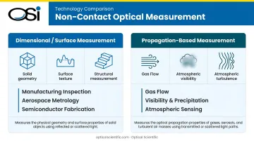
In dimensional systems, the instrument interrogates a solid surface and reconstructs its geometry from reflected signals. In propagation-based systems, the instrument analyzes how a light beam changes as it passes through a medium — using scattering, scintillation, Doppler shift, or absorption to characterize what the light traveled through.
Each family contains multiple sub-techniques, and the right choice depends on the target material, required accuracy, and operating environment — topics the rest of this guide covers in detail.
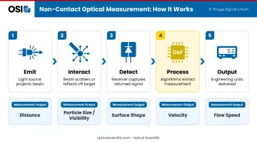
How Does Non-Contact Optical Measurement Work?
All non-contact optical systems — from white-light interferometers to airport visibility sensors — follow the same fundamental sequence: emit, interact, detect, process, output.
Signal Emission
The process begins with a calibrated light source projecting energy toward the target. Common source types include:
- Coherent lasers — narrow wavelength, high intensity; used for triangulation, Doppler sensing, and interferometry
- Infrared LEDs — solid-state, low-power; used in forward scatter and scintillation sensors for continuous outdoor operation
- Structured light patterns — projected grids or fringes used to encode surface geometry
- Broadband white light — used in interferometers for sub-nanometer surface profiling
Emission parameters — wavelength, pulse duration, intensity, beam angle — are not arbitrary. They are chosen to maximize signal-to-noise ratio for the specific target material or medium. OSI's optical sensors, for example, use infrared LED sources specifically because IR reduces interference from ambient visible light and provides effective penetration through atmospheric conditions while remaining compatible with solid-state photodiode detection.
Detection & Data Capture
As emitted light interacts with the target, detectors — photodiodes, CCD/CMOS arrays, or photodetectors — capture the returned or transmitted signal. What gets encoded in that returned signal depends on the technique:
- Time-of-flight → distance (NIST Technical Note 1682 reports pulsed TOF range uncertainty of 5–50 mm; frequency-modulated TOF achieves 0.01–0.25 mm)
- Scatter intensity and angle → particle size and concentration (visibility in meters or RVR)
- Fringe deformation → surface shape at nanometer resolution
- Doppler frequency shift → velocity of a moving surface or particle
- Scintillation pattern fluctuations → flow velocity, crosswind speed, and atmospheric turbulence strength
Detector quality and optical path precision directly determine measurement resolution, range, and sensitivity. OSI addresses this by pairing precision optics with thermally stable designs and ruggedized field housings built for harsh deployment environments.
Signal Processing & Calibration
Digital signal processors apply algorithms to convert raw photon counts or waveform data into engineering units — millimeters, meters per second, grams per cubic meter, visibility in RVR.
Calibration is built into well-designed systems rather than scheduled periodically. OSI's all-digital DSP-based design eliminates temperature-sensitive analog components entirely — a meaningful distinction in harsh deployments. Analog components drift as temperature changes; digital signal processing does not.
That design choice has real-world consequences. OSI's OFS optical flow sensors have recorded no instances of calibration fault since 1999, and their scintillation algorithms automatically compensate for partial lens contamination from dust, water droplets, or ice accumulation. The system triggers a fault alarm if drift exceeds 3% from norm, and internal monitoring alerts operators when window cleaning is needed — typically only semi-annually even in the dirtiest stack applications.
Output & Integration
The system delivers a real-time, quantified measurement formatted for downstream use. OSI's OFS and OWI series instruments support:
- RS-232 and Modbus RTU (standard)
- RS-485, Ethernet, and cellular modems (optional)
- Integration with SCADA, DCS, and data acquisition systems, including EPA 40 CFR Part 75 compliance reporting platforms
Key Types of Non-Contact Optical Measurement Devices
The device category used depends on what is being measured. Here is a practical decision map across the five main types.
Laser Scanning & 3D Optical CMMs
Laser scanners and optical coordinate measuring machines (CMMs) project a laser beam or structured light pattern onto a solid surface, capture reflected geometry with high-resolution cameras, and reconstruct dimensional data in 2D or 3D.
Accuracy ranges by method (NIST Technical Note 1682):
- Active triangulation: 0.02–2.00 mm
- Pulsed time-of-flight: 5–50 mm
- Frequency-modulated TOF: 0.01–0.25 mm
These systems are governed by ISO 10360-13:2021 (optical 3D coordinate measuring systems) and ASTM E57 (3D imaging systems including laser scanners). In aerospace, optical laser probes mounted on high-precision CMMs have been used to speed the measurement of precision turbine blades — a contact probe would be slower and risk damaging fine blade geometry.
Key tradeoff: optical scanners are faster and non-damaging but can be affected by surface reflectivity and require controlled lighting. Contact CMMs remain preferred for opaque, complex internal geometries.
Interferometers & Optical Profilers
White light interferometry splits a beam, recombines reference and measurement paths, and analyzes the resulting fringe pattern to measure surface topography. NIST reports coherence scanning interferometry achieves approximately 3 nm vertical resolution and 1 micrometer lateral resolution.
For semiconductor fabrication, NIST's XCALIBIR system uses a 633 nm interferometer to evaluate 300 mm silicon wafer flatness with approximately 1 nm rms surface-height uncertainty — a tolerance impossible to achieve with any contact method.
Forward Scatter Visibility & Precipitation Sensors
A transmitter emits a light beam; a receiver positioned at an angle captures light scattered by particles — water droplets, ice crystals, dust — passing through the sensing volume. Scatter intensity converts to visibility in meters or RVR, and scatter characteristics identify precipitation type.
This is the operating principle behind RVR systems at airports. FAA Order 6560.10D specifies that modern RVR systems use scatter-effect technology with infrared projectors and receivers, reporting in 100 ft increments below 800 ft and 200 ft increments up to 3,000 ft. The NWS ASOS visibility sensor operates on the same forward-scatter principle, deployed across approximately 950 ASOS sites in the United States.
OSI's OWI-430 DSP-WIVIS uses a triple aperture optical system combining forward scatter visibility measurement with in-beam optical scintillation for precipitation type discrimination. The sensor detects rain, snow, drizzle, freezing rain, sleet, and hail — reporting over 50 NWS and WMO weather codes — while simultaneously measuring meteorological optical range for RVR calculations.
Optical Scintillation Sensors
When light travels through a turbulent medium — flowing gas, crosswind, or atmospheric boundary layer — it experiences intensity fluctuations called scintillation. Analyzing those fluctuations with a receiver and DSP algorithms extracts flow velocity, crosswind speed, and turbulence strength without any probe in the flow path.
This makes scintillation-based measurement well suited to environments where inserting a contact probe is physically impossible or operationally unacceptable: hot corrosive stack gas, high-velocity flue streams, airspace above a runway, or hydrogen fluoride atmospheres in aluminum smelter pot rooms.
OSI's patented optical scintillation technology (Patent US 05444530) operates on this principle. Three characteristics set it apart from other measurement methods:
- Measures turbulence directly, not as an inference from temperature, pressure, gas density, or opacity — giving consistent readings across widely varying process conditions
- Requires no calibration by its physical nature; OSI's OFS sensors have recorded no calibration faults since 1999
- Tolerates partial obscuration — turbulence fluctuations remain detectable with only a fraction of transmitted light, maintaining accuracy even with contaminated optics
The OFS-2000 measures stack gas flow at ±2% accuracy over a 0–100 m/sec range. The OFS-2000F extends this to 0.03–170 m/sec for flare applications.
The same scintillation principle scales to atmospheric distances. OSI's LOA (Long-Baseline Optical Anemometer) measures crosswinds and Cn² atmospheric turbulence over path lengths up to 10 km, with installations at airport runways, refinery fence lines, and aluminum smelter facilities. A 2015 peer-reviewed study in Boundary-Layer Meteorology placed an optical scintillometer alongside a runway at Schiphol Airport to detect wake vortex, crosswind, and visibility conditions simultaneously.

Laser Doppler Vibrometers & Velocimeters
Doppler-based optical sensors use the frequency shift of laser light reflected from a moving surface or particle to measure vibration, displacement velocity, or fluid/gas velocity. NIST SP 250-79 describes laser Doppler anemometry measuring particle velocity from Doppler frequency shift, with shock calibration results agreeing with mechanical displacement within ±0.1% above 10,000 m/s².
Applications include aerospace structural testing, vibration analysis, and traffic speed monitoring.
Where Non-Contact Optical Measurement Is Used
The deployment environment — not just the measurement principle — determines which method is appropriate.
Controlled Indoor Environments
Manufacturing floors, cleanrooms, and metrology labs are where dimensional and surface measurement tools dominate. Laser scanners and optical CMMs inspect machined parts, turbine blades, and additive manufacturing outputs against ISO 10360-13 and ASTM E57 standards. Interferometers handle semiconductor wafers and precision optics at nanometer tolerances.
Semi-Controlled Industrial Environments
Power plant stacks, refineries, chemical plants, and aluminum smelters require optical flow and scintillation sensors capable of operating in chemically aggressive, high-temperature, variable-opacity conditions where contact probes would fail or require impractical maintenance schedules.
EPA 40 CFR Part 75 mandates continuous monitoring of SO₂, NOₓ, CO₂, volumetric flow, and opacity from fossil-fuel electric generating units greater than 25 MW. OSI's OFS series supports Part 75 compliance using NIST-certified algorithms and drift-free optical measurement. Customers in this space include Duke Energy, Dominion Virginia Power, ExxonMobil, Chevron, and Shell Chemical.
Uncontrolled Outdoor Environments
Airports, highways, maritime ports, and weather stations require sensors that operate continuously in all weather conditions with minimal maintenance access:
- Aviation: FAA-certified AWOS systems and OWI series sensors for RVR, present weather, and crosswind data
- Transportation: FHWA Road Weather Information System (RWIS) Environmental Sensor Stations use optical visibility sensors to detect low-visibility conditions and trigger highway alerts
- Maritime: OSI's ORG optical rain gauges operate on NOAA buoys in North Atlantic conditions, with MTBF exceeding 80,000 hours — roughly 9.1 years of continuous operation
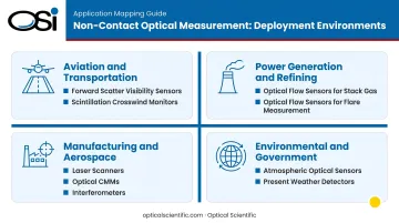
Industry-to-device mapping:
| Industry | Primary Device Type |
|---|---|
| Aviation & transportation | Forward scatter visibility sensors, scintillation crosswind monitors |
| Power generation & refining | Optical flow sensors (stack gas, flare) |
| Manufacturing & aerospace | Laser scanners, optical CMMs, interferometers |
| Environmental & government agencies | Atmospheric optical sensors, present weather detectors |
Conclusion
Non-contact optical measurement is a family of techniques unified by one physical principle: using light to extract precise, real-time data without disturbing what is being measured. Whether the target is a machined turbine blade, a column of flue gas, or the atmosphere above a runway, the right technique depends on the nature of the medium, the required accuracy, and the operating environment.
Engineers and operators who understand these distinctions are better positioned to select instruments that deliver long-term reliability without maintenance burden.
An optical scintillation sensor that never requires calibration and carries a 9-year MTBF serves a different operational requirement than a laser scanner that needs controlled lighting and periodic field verification — even though both are "non-contact optical" systems.
Getting that distinction right at specification time reduces mismatches, avoids costly retrofits, and keeps critical infrastructure running reliably for years after installation.
Frequently Asked Questions
What is non-contact optical measurement?
Non-contact optical measurement uses light-based technologies — lasers, LEDs, structured light, or broadband radiation — to measure physical properties such as dimensions, flow velocity, visibility, and surface texture without touching the target. It covers both dimensional metrology (manufacturing, semiconductor inspection) and propagation-based sensing (flow monitoring, atmospheric measurement, precipitation detection).
What is non-contact optical speed measurement?
Non-contact optical speed measurement determines the velocity of an object, fluid, or gas by analyzing how a light signal changes after interacting with a moving target. The two main mechanisms are Doppler frequency shift (used in laser Doppler velocimeters) and scintillation pattern analysis (used in optical anemometers and stack gas flow sensors), both eliminating any probe inserted into the flow path.
What is the difference between a VMM and a CMM?
A CMM (Coordinate Measuring Machine) uses a physical probe that touches the part surface to collect dimensional data. A VMM (Video Measuring Machine) uses cameras and optical sensors to capture the same data without contact. VMMs are faster and non-damaging, though CMMs remain preferred for complex internal geometries where optical access is restricted.
What are the main advantages of non-contact optical measurement over contact methods?
Key advantages over contact methods include:
- No risk of surface damage or contamination
- Compatible with soft, hot, or chemically reactive materials and gases
- Higher throughput with continuous, maintenance-free operation
- Able to measure hazardous or physically inaccessible environments
What industries rely most heavily on non-contact optical measurement?
Aviation (RVR and crosswind monitoring), manufacturing and aerospace (dimensional inspection and surface metrology), power generation and refining (stack gas flow for emissions compliance), transportation (road weather visibility sensors), and environmental and government monitoring agencies including NASA, NOAA, and the EPA.
How accurate is non-contact optical measurement?
Accuracy depends on technique: interferometers achieve roughly 3 nm vertical surface resolution, laser scanners reach 0.01–2.00 mm dimensional accuracy, and optical flow sensors such as OSI's OFS series deliver ±2% for stack gas velocity. Systems with built-in self-diagnostics maintain that accuracy over time without field recalibration.