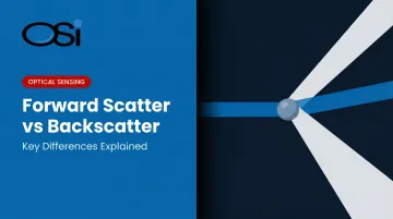
Forward scatter and backscatter are the two optical geometries at the heart of modern visibility sensors. Both measure how light interacts with atmospheric particles, but they do it from fundamentally different angles — literally. The geometry you choose determines signal strength, measurement range, installation complexity, and whether your system meets applicable standards like FAA AC 150/5220-16E or ICAO Doc 9328.
This article breaks down how each technology works, where each performs best, and how to match the right geometry to your application.
Key Takeaways
- Forward scatter separates the transmitter and receiver across a sample volume, measuring light deflected at 30–50° for a stronger signal and wider measurement range
- Backscatter houses both components in one unit and measures light returned toward the source; one-unit installation suits moderate-range threshold applications well
- Forward scatter is the default for aviation RVR reporting, highway safety systems, and any application requiring calibrated MOR across a wide visibility range
- Backscatter excels in ceilometers, remote RWIS nodes, and threshold-detection applications where installation simplicity outweighs precision
- Sensor selection hinges on measurement range, accuracy requirements, site conditions, and applicable regulatory standards
Forward Scatter vs Backscatter: Quick Comparison
The table below compares forward scatter and backscatter sensors across the specifications that drive real-world deployment decisions — from signal strength and measurement range to regulatory fit and installation requirements.
| Criterion | Forward Scatter | Backscatter |
|---|---|---|
| Optical geometry | Transmitter and receiver separated at 30–50° | Transmitter and receiver in single housing, ~180° return |
| Signal strength | Higher — captures dominant Mie scatter lobe | Weaker — smaller fraction of scattered energy returned |
| Measurement range | Wide — commercial sensors reach 40 km to 100 km MOR | Narrower — research prototypes demonstrated to ~1,200 m reliably |
| Low-visibility performance | Strong — maintains signal in dense fog, heavy snow | Variable — ICAO Doc 9328 notes abnormally high backscatter response in snow |
| Installation | Requires aligned dual-head mounting | Single-head unit, faster to install |
| Regulatory fit | Preferred for aviation RVR and ICAO-standard visibility | Standard for ceilometers and moderate-accuracy RWIS nodes |
| Primary use | Airport AWOS, RVR, highway RWIS, NWS observation | Cloud base detection, remote stations, threshold alerting |
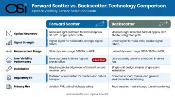
MOR range figures reflect commercial instrument specifications; actual performance depends on sensor model, calibration interval, and operating environment.
What Is Forward Scatter?
The Physics
When light strikes a particle, the energy doesn't scatter equally in all directions. For particles comparable to or larger than the light's wavelength — fog droplets, drizzle, dust — Mie scattering governs the interaction, and the bulk of scattered energy concentrates in the forward direction.
Forward scatter visibility sensors exploit this directly. The transmitter (typically an infrared LED or laser diode) directs a modulated beam across a defined sample volume. A separate receiver, positioned off-axis from the beam, captures the light deflected at angles typically between 30° and 50° — the range specified in ICAO Doc 9328 for visibility meters, with 40° commonly used for fog and snow measurement consistency.
Because the receiver sits in the dominant scatter lobe, it captures significantly more signal than a backscatter arrangement. Backscatter collects only the small fraction of energy redirected toward the source — a meaningful disadvantage in dense obscuration conditions.
Operational Performance
That signal advantage translates directly to measurement capability:
- Dense fog: Forward scatter maintains adequate signal even when visibility drops below 100 meters
- Heavy snow and drizzle: Strong forward-directed return allows the instrument to distinguish light obscuration from clear air
- High visibility: Wide dynamic range supports measurement up to 40–100 km MOR depending on the instrument
A peer-reviewed forward scatter study achieved a 0.9998 correlation at a 35° scatter angle, with ±11.7% RMS error, confirming the geometry's measurement stability across conditions.
OSI's OWI-430 series puts this geometry to work using an infrared LED transmitter with a triple aperture optical system. One receiver detects present weather via in-beam optical scintillation; a second dedicated receiver measures visibility through off-axis forward scatter. The dual-receiver design pulls data from forward scatter, in-beam scintillation, ambient light, temperature, and humidity simultaneously, improving discrimination across all weather types.
Use Cases
Primary deployment environments:
- Airport AWOS/ASOS systems and runway visual range (RVR) reporting
- Highway road weather information systems (RWIS) on high-risk corridors
- NWS and NOAA meteorological observation networks
- Maritime port and harbor visibility monitoring
- Military weather stations requiring continuous, reliable observation
OSI's deployments span both aviation and surface transportation. The FAA-certified AWOS-AV system incorporates dual forward scatter visibility sensors and complies with FAR 91.171 and FAR 91.175; the OWI series is deployed at airports across the US and internationally. On the highway side, state DOTs in Maryland, Ohio, Wyoming, Vermont, Wisconsin, and New Hampshire use OSI's OWI-430 DSP-WIVIS and OWI-650 LP-WIVIS sensors in RWIS networks for real-time visibility and precipitation type monitoring.
What Is Backscatter?
The Physics and Hardware
In a backscatter sensor, the transmitter and receiver share a single housing. The transmitter fires a beam into the atmosphere; the receiver captures the fraction of light redirected back at roughly 180° from the original beam direction.
The immediate consequence: the received signal is weaker. Backscattered energy represents a much smaller portion of total scattered light than what a forward-positioned receiver would capture. To compensate, backscatter instruments often use more sensitive photodetectors — sometimes avalanche photodiodes — to pull usable signal from the return.
This single-head design eliminates the need to align separated optical heads — a meaningful advantage on highway gantries, remote buoy platforms, or space-constrained urban installations where running conduit to two mounting points is impractical.
Performance and Limitations
That installation simplicity comes with performance trade-offs. ICAO Doc 9328 specifically flags two backscatter caveats:
- Variable response to fog — backscatter return doesn't scale as predictably with fog density as forward scatter
- Abnormally high response to snow — the retroreflective character of snowflakes inflates backscatter readings
A peer-reviewed backscatter visibility prototype using an 808 nm pulsed laser demonstrated reliable estimation over 100 to 1,200 meters, with a theoretical ceiling near 3,500 meters. Sufficient for threshold-detection work — but well short of the 10 km+ range required for aviation RVR certification.
In very clean air, the backscattered signal can approach the instrument noise floor, limiting range resolution at the high-visibility end as well.
Use Cases
Backscatter's installation simplicity and cost profile make it the practical default in specific contexts:
- Ceilometers — measuring cloud base height and vertical visibility. The Campbell CS135 LIDAR ceilometer, for example, uses a 912 nm laser to profile clouds up to 10 km with 5-meter resolution
- Remote RWIS nodes — single-head sensors on highway gantries where running conduit to two mounting points is impractical
- Low-power deployments — solar or battery-powered remote stations where the simpler optical path reduces power draw
- Threshold alerting — applications that need to flag "poor visibility" vs. "acceptable visibility" rather than report a calibrated MOR value
- Research lidar systems — atmospheric profiling using backscatter returns to characterize aerosol layers vertically
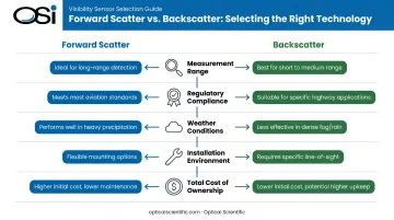
Forward Scatter vs Backscatter: Which Is Right for Your Application?
Five Decision Variables
Neither technology universally outperforms the other. The right answer depends on:
- Required measurement range and resolution — RVR reporting needs 50 m to 2,000 m+ with 25-meter increments at low end; threshold alerting needs far less
- Accuracy and regulatory compliance — FAA and ICAO specify performance envelopes that forward scatter instruments are well-positioned to meet
- Weather conditions at the site — heavy snow environments particularly favor forward scatter given backscatter's abnormal snow response
- Installation environment — dual-head mounting requires structural support and alignment; single-head backscatter eliminates that requirement
- Total cost of ownership — forward scatter instruments may cost more upfront but avoid the accuracy limitations that require supplemental sensors
Choose Forward Scatter When:
- The application requires FAA, ICAO, or equivalent regulatory certification
- The site reports dense fog, heavy snow, or other extreme low-visibility events
- Output feeds a safety-critical system — RVR reporting, automated highway warning signs, NWS observations
- Calibrated MOR values across a wide range are required, not just threshold detection
Choose Backscatter When:
- Installation simplicity is the primary constraint
- The application is a ceilometer (cloud base detection, not MOR)
- Budget favors a single-head instrument and moderate accuracy is sufficient
- The site primarily needs to distinguish significant visibility degradation, not report precise MOR
Hybrid Deployments
Many complete weather observation stations pair both technologies. The U.S. ASOS network (a joint NWS, FAA, and DOD program with more than 900 stations operating continuously at airports) uses a forward scatter visibility sensor for MOR/present weather measurement alongside a separate laser beam ceilometer for cloud base height.
The ASOS User Guide identifies these as distinct instruments serving distinct functions: the visibility sensor measures meteorological optical range, the ceilometer measures cloud height to 12,600 feet.
This combination gives a single station complete atmospheric state data — visibility, precipitation type, and cloud base — without one technology trying to do everything.
For installations following this multi-sensor model, OSI's sensor platforms include reserved I/O that allows additional instruments to share a single data acquisition system, avoiding redundant hardware costs.
Real-World Applications
Airport AWOS: Where Forward Scatter Is Non-Negotiable
An airport operating in a fog-prone region needs RVR data reported in increments of 25 meters below 400 meters — the precision required by ICAO Doc 9328 for low-visibility approach operations. A backscatter sensor with a practical reliable range of 1,200 meters simply can't cover the full reporting envelope.
OSI's AWOS-AV system addresses this with dual forward scatter visibility sensors, dual pressure sensors, and continuous 24/7 automated reporting. It is FAA-certified, complies with FAR 91.171 and FAR 91.175, and transmits real-time weather data directly to air traffic control.
OSI has deployed these systems at airports and private helipads across the US. The OWI-430 series carries an MTBF exceeding 80,000 hours, making it a practical fit for infrastructure where unplanned downtime isn't an option.
Highway RWIS: Where Backscatter Makes Sense
A state DOT deploying 40 visibility sensors across a mountain highway corridor faces a different calculation. Each sensor needs to mount on an overhead gantry and connect to a dynamic message sign controller. The primary function: detect when fog or blowing snow drops visibility below a warning threshold.
Here, a single-head backscatter sensor offers faster installation per node, lower per-unit cost, and adequate accuracy for binary alerting. The tradeoff — reduced precision in heavy snow — is acceptable when the output triggers a "REDUCED VISIBILITY — SLOW DOWN" sign rather than feeds an RVR report to approach control.
That said, OSI's OWI-430 DSP-WIVIS and OWI-650 LP-WIVIS — both forward scatter designs — are also deployed in RWIS networks by multiple state DOTs precisely because the same sensor that handles threshold alerting can simultaneously report calibrated MOR for highway weather data archives and compliance documentation.
Choosing between the two geometries comes down to what your data needs to do after it's collected. Contact OSI to discuss how forward scatter or multi-sensor configurations can be matched to your specific site, regulatory, and operational requirements.
Conclusion
Forward scatter and backscatter aren't competing standards — they're complementary tools for different performance envelopes. Forward scatter delivers greater measurement range, stronger signal, and better precision in extreme weather. Backscatter offers simpler installation and lower cost for moderate-accuracy, threshold-detection applications.
Choosing the wrong geometry upfront creates problems that compound over time: missed regulatory thresholds, reduced accuracy in the exact conditions that matter most, or costly hardware swaps. The variables that should drive the decision are:
- Measurement range and accuracy requirements
- Site weather patterns and expected visibility extremes
- Installation constraints (single-ended vs. dual-ended mounting)
- Whether output feeds a safety-critical or compliance-reporting function
For aviation, highway safety, and industrial monitoring applications, getting that match right from day one reduces long-term maintenance burden, protects regulatory compliance, and ensures visibility data holds up precisely when conditions deteriorate and measurement accuracy is most consequential.
Frequently Asked Questions
What does forward scattering mean?
Forward scattering is the deflection of light by a particle at small angles so that the light continues traveling in roughly the same direction as the original beam. It contrasts with backscatter, which redirects light back toward the source, and side scatter, which redirects it at approximately 90°. In atmospheric visibility sensing, forward scatter dominates when Mie scattering governs the interaction.
What are the three types of scattering?
The three primary scattering regimes are Rayleigh scattering (sub-wavelength particles like gas molecules), Mie scattering (particles near or larger than the wavelength, such as fog droplets and dust), and geometric scattering (large particles where reflection and refraction dominate). Visibility sensors operate primarily in the Mie regime.
Which is more accurate: forward scatter or backscatter sensors?
Forward scatter sensors generally deliver higher accuracy and wider dynamic range, particularly at low visibility, because they capture a stronger portion of the scattered signal. Backscatter sensors are accurate enough for moderate-range applications but can lose resolution at both extremes — very clear air and very dense obscuration.
What is a backscatter sensor used for?
Backscatter sensors are used in ceilometers for cloud base height detection, road weather information systems, and atmospheric lidar profiling. They suit applications where single-head installation simplicity is the priority over calibrated MOR (Meteorological Optical Range) reporting.
Can forward scatter sensors work in heavy rain or snow?
Yes. Forward scatter sensors are designed for reliable operation in heavy precipitation — rain, snow, drizzle, and fog — because the strong forward-directed Mie scatter signal holds up even in dense obscuration. That makes them the standard choice for aviation and highway safety applications.