Introduction
Selecting the wrong stack gas flowmeter is a compliance liability, not just a technical one. Industrial facilities operating under EPA regulations must continuously monitor and report stack gas flow rates as part of certified Continuous Emission Monitoring Systems (CEMS). Get the flowmeter wrong, and you're looking at inaccurate emissions data, failed audits, and regulatory penalties.
Stack environments make this harder than standard gas metering. Exhaust gases carry particulates, moisture, and chemically variable compositions across duct cross-sections that often exceed several meters in diameter.
These conditions disqualify several common flow technologies outright. A poor match — fouled sensors, process shutdowns, missing CEMS data — compounds over years of continuous operation.
This guide walks through the four primary flowmeter technologies used in stack gas measurement, the selection factors engineers must evaluate, and how to match the right technology to your stack's specific conditions.
Key Takeaways
- Stack gas flow measurement is mandatory under 40 CFR Part 75 and 40 CFR Part 98, converting pollutant concentrations into reportable mass emissions
- Main technologies: differential pressure/pitot tube, thermal mass, ultrasonic, and optical scintillation (magnetic flowmeters do not work on gases)
- Key selection factors: gas composition and temperature, particulate/moisture loading, stack geometry, and regulatory performance specs
- Flow monitor relative accuracy must not exceed 10.0% under Part 75 RATA requirements — datasheet accuracy alone is not enough
- This guide maps each technology's strengths and limitations to specific process conditions so you can make a defensible selection
What Is Stack Gas Flow Measurement?
Stack gas flow measurement is the continuous measurement of exhaust gas velocity and volumetric flow rate within an industrial stack or duct. The data is used to calculate total pollutant mass emissions — SO₂, NOₓ, CO₂ — required for regulatory reporting.
The regulatory framework is specific. Under 40 CFR Part 75, affected units must install an SO₂ CEMS plus a certified flow monitoring system with a data acquisition and handling system (DAHS) that records SO₂ concentration, stack gas volumetric flow in scfh, and SO₂ mass emissions in lb/hr.
Under 40 CFR Part 98 Tier 4, facilities emitting 25,000 metric tons CO₂e or more annually must pair a CO₂ concentration monitor with a stack gas volumetric flow rate monitor.
Each CEMS must complete at least one cycle of operation for each successive 15-minute interval. Hourly averages require at least one data point in each 15-minute quadrant when the unit combusts fuel — meaning your flowmeter is never "off duty."
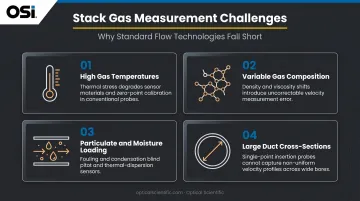
Several physical and chemical conditions at the stack make this measurement category technically distinct from standard industrial flow applications:
- Gas temperatures vary significantly by process and control train (site-specific, not a universal range)
- Chemically variable compositions including SO₂, CO₂, water vapor, and acid gases
- Particulate and moisture loading that degrades or physically blocks many sensor types
- Large duct cross-sections — often 1–5 meters or more — requiring spatially representative measurements
Together, these conditions eliminate contact-based and mechanically sensitive flow technologies from consideration — leaving a narrow field of sensor types capable of reliable, continuous compliance-grade measurement.
Types of Flowmeters Used for Stack Gas Measurement
Differential Pressure / Averaging Pitot Tube
EPA Method 2 (formally titled "Determination of Stack Gas Velocity and Volumetric Flow Rate (Type S Pitot Tube)") establishes the DP/pitot approach as the foundational reference method for manual stack testing. Averaging pitot systems extend this concept to continuous monitoring.
The practical limitation is plugging. EPA Method 2 explicitly states that standard pitot static and impact pressure holes are prone to plugging in particulate-laden gas streams. In CEMS applications, this means daily interference checks are required under Part 75 Appendix B, and auto-purge systems using timed compressed-air back-purge are a standard mitigation.
NIST testing showed S-probe RATA deviations of 5–6% in stack simulator conditions, with a 12-point traverse overpredicting by 6.1% at low load. Thorough traverse design, purge systems, and pluggage detection are non-negotiable for DP systems in dirty stacks.
Best for: Clean or moderately clean gas streams where cost is a primary driver and purge systems can be reliably maintained.
Thermal Mass Flowmeters
Thermal dispersion meters measure mass flow directly by sensing how much a heated RTD element is cooled by the passing gas, delivering a direct mass flow reading without separate pressure and temperature transmitters. They have no moving parts and handle low-flow conditions well.
The limitation in stack service is fouling. Particulate buildup on the sensing element degrades accuracy progressively, and condensed moisture can cause immediate performance problems. Model-specific configurations for wet or dirty gas exist from manufacturers like Kurz Instruments and Sierra, but you must verify suitability against actual stack conditions.
Thermal meters also require gas-specific calibration factors. A meter calibrated for air behaves differently in streams with varying CO₂, water vapor, or SO₂ concentrations — an important consideration in stack gases where composition shifts with load or fuel type.
Best for: Relatively clean gas streams with stable composition and reliable access for periodic sensor cleaning.
Ultrasonic Flowmeters
Ultrasonic transit-time meters measure flow velocity across the stack diameter without any in-stack probe, making them non-intrusive and well-suited for large-diameter ducts. Products like the DURAG D-FL 220 are rated for duct temperatures up to 300°C and humidity up to 100%, including condensation.
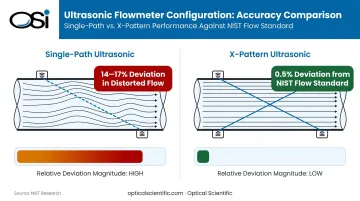
The critical performance variable is flow profile. NIST research found that a single-path ultrasonic CEMS deviated 14–17% in highly distorted flow, while an X-pattern configuration achieved only 0.5% deviation from the NIST flow standard. This difference is decisive: single-path ultrasonic systems in non-uniform stacks can fail RATA requirements even if the transducers themselves are performing correctly.
Best for: Large-diameter stacks with relatively uniform flow profiles, or where multi-path X-pattern configurations can be installed.
Optical / Scintillation-Based Flowmeters
Optical flow sensors represent a fundamentally different measurement approach. OSI's OFS series, developed in 2000 specifically for EPA 40 CFR Part 75 compliance at power plants, uses patented optical scintillation technology to detect turbulence movement in the gas stream via infrared light fluctuations, rather than relying on particle scattering, differential pressure, or thermal effects.
The measurement principle is unaffected by distance, pressure, temperature, gas density, moisture, or opacity, and requires no gas-specific calibration factors. This is a meaningful operational advantage in stacks where composition or temperature shifts with load.
These properties translate directly into a set of practical design features that distinguish the OFS in continuous monitoring applications:
- No moving parts and no wetted sensing elements in the gas stream
- Automatic Gain Control (AGC) circuitry compensates for optical surface contamination, with window cleaning typically needed only semi-annually even on dirty stacks
- Built-in continuous self-test with automated fault alarms triggered if drift exceeds 3% from baseline
- NIST-certified algorithm supported by over 20 million hours of observation data
- MTBF exceeding 80,000 hours, with no instances of calibration fault recorded since 1999
- Three model variants: OFS-2000 (standard stack, 0–100 m/sec), OFS-2000F (flare stacks, 0.03–170 m/sec), OFS-2000W (wet scrubbers and high-opacity environments, equipped with AGC)
Best for: Continuous 24/7 CEMS operation in high-particulate, high-temperature, or chemically aggressive stacks where unattended reliability and minimal maintenance are priorities.
What Cannot Be Used — And Why
Magnetic flowmeters operate on electromagnetic induction and require an electrically conductive liquid medium. Stack gas is not a conductive liquid. Electromagnetic flowmeters are designed for water, acids, alkalis, and slurries; they have no application in any gas measurement context.
Key Factors to Consider When Selecting a Stack Gas Flowmeter
A coal-fired power plant stack differs substantially from a chemical plant vent or a waste incinerator exhaust. Selection requires systematic evaluation of your specific conditions against each technology's documented strengths and limitations.
Gas Temperature and Composition
Stack gas temperatures are site-specific and depend on the process and any upstream control equipment. Sensor components must be rated for continuous exposure at operating temperatures without degrading accuracy or structural integrity. Material selection — 316L stainless, Hastelloy, or ceramic-coated probes for acid gas service — is critical in streams containing SO₂ or HCl.
Gas composition drives calibration requirements just as much as temperature does. Thermal mass meters require gas-specific calibration factors that must be updated when composition shifts. The OFS scintillation measurement principle is explicitly independent of gas composition, density, and temperature changes, so no recalibration is needed when stack gas constituents vary with load or fuel.
Particulate Loading and Moisture Content
Particulate concentration is often the single most decisive factor in technology selection:
- DP/pitot systems: Ports plug in high-dust streams; auto-purge systems and daily interference checks are required
- Thermal mass meters: Sensing elements foul progressively; sensor cleaning frequency must match actual particulate load
- Ultrasonic meters: High particulate or moisture can scatter or attenuate the acoustic beam; transducer maintenance access is critical
- Optical scintillation (OFS): AGC circuitry compensates for contaminated optics; no wetted sensing elements contact the gas stream
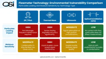
Moisture compounds particulate problems. Wet particles adhere to sensors and form scale deposits. In wet stack environments, dirt-tolerant designs or those with no direct gas contact reduce maintenance burden substantially.
Stack Size and Installation Constraints
EPA Method 1 siting criteria recommend at least 8 stack diameters downstream and 2 diameters upstream from a flow disturbance. Part 75 Appendix A allows a minimum of 2 diameters downstream and 0.5 diameter upstream with a supporting flow-profile study — but EPA recommends conducting flow-profile studies at three operating levels to confirm location acceptability.
Where adequate straight run isn't available:
- Multi-point or averaging sensor designs distribute measurements across the duct cross-section
- X-pattern ultrasonic configurations reduce profile sensitivity significantly
- The OFS provides path-averaged velocity across the full stack diameter with a minimum installation requirement of only 2 upstream and 1 downstream diameter
Physical access for maintenance matters too. Insertion-style sensors that retract through a ball valve without process shutdown are operationally superior to inline spool-piece designs that require extended outages for servicing in a 24/7 CEMS application.
Regulatory Compliance and Performance Specifications
Part 75 Appendix A requires flow monitor relative accuracy not to exceed 10.0% at any tested load level. RATA frequency is generally semiannual; annual frequency applies if relative accuracy is ≤7.5% at each tested operating level. Daily calibration error must not exceed 3.0% of calibration span, with readings above 6.0% considered out-of-control.
These aren't datasheet numbers — they're field performance thresholds that must be met under actual operating conditions, repeatedly, over the life of the instrument.
QA burden also varies by technology:
| QA Requirement | Frequency | Notes |
|---|---|---|
| Daily calibration check | Daily | ≤3.0% of calibration span |
| Daily interference check | Daily | Pluggage detection for DP; transceiver check for ultrasonic |
| Quarterly flow-to-load evaluation | Quarterly | All flow monitors |
| DP sample line leak check | Quarterly | DP flow monitors only |
| RATA | Semiannual (annual if ≤7.5%) | All CEMS flow monitors |
Built-in self-diagnostics, automated fault alarming, and continuous self-test reduce the manual burden of meeting these requirements. For a 24/7 CEMS application, those capabilities aren't optional extras — they're what keeps the system in compliance between audits.
Total Cost of Ownership
Purchase price is the least informative metric for CEMS flowmeter evaluation. The real cost drivers over a 10–20 year service life include:
- Semiannual third-party RATA audits are expensive; qualifying for annual frequency at ≤7.5% relative accuracy cuts that cost in half
- Daily and quarterly QA labor — interference checks, calibration verification, flow-to-load evaluations — accumulates quickly across a multi-unit facility
- DP meters require compressed air supply infrastructure for purge systems, adding ongoing operational cost
- Thermal and wetted sensors in dirty stacks require periodic cleaning and eventual element replacement
- Out-of-control periods and missing data affect compliance standing and may trigger substitute data calculations
In high-particulate environments, instruments without moving parts or wetted sensors typically deliver lower lifecycle costs despite higher upfront pricing. The savings on labor, purge infrastructure, and sensor replacement often offset the initial price difference within the first few years of operation.
How OSI Can Help
For facilities that need a proven, low-maintenance solution for stack gas flow, Optical Scientific, Inc. (OSI) has been developing advanced optical sensor technology since 1985. In 2000, OSI developed the OFS series specifically to address continuous stack gas flow monitoring for EPA 40 CFR Part 75 compliance at power plants.
The OFS has since been deployed at facilities operated by Duke Energy, Dominion Virginia Power, Detroit Edison, and Alliant Energy, as well as industrial clients including Covanta Energy, Shell Chemical, Chevron, and ExxonMobil.
The OFS uses patented optical scintillation technology — no probes, no moving parts, no direct contact with corrosive or particulate-laden gas streams. The system measures turbulence-induced light fluctuations across the full stack diameter, delivering path-averaged velocity at ±2% accuracy without gas-specific calibration.
OFS advantages for CEMS applications:
- No scheduled optical cleaning required; AGC circuitry compensates automatically for dirty optics
- Measurement unaffected by temperature, pressure, gas density, moisture, or opacity changes
- Continuous self-test with automated fault alarm if drift exceeds 3%; no calibration faults recorded since 1999
- NIST-certified measurement algorithm supported by over 20 million hours of observation data
- MTBF exceeding 80,000 hours, designed for 24/7/365 unattended operation
- RS-232/Modbus RTU standard output; RS-485, Ethernet, and cellular options available for CEMS DAHS integration
- Minimum installation requirement of 2 upstream / 1 downstream diameters
- ISO 9001:2015 certified manufacturing; trusted by EPA, NASA, NOAA, and major energy companies
OSI offers purpose-built variants for demanding environments:
- OFS-2000W — adds AGC for wet scrubber and high-opacity environments
- OFS-2000F — extends velocity range to 0.03–170 m/sec for flare stack applications
All variants share the same core scintillation principle: no moving parts, no field calibration required.
Conclusion
Selecting a stack gas flowmeter is a compliance and operational risk decision. The technology you install must match the specific combination of temperature, particulate loading, duct geometry, regulatory requirements, and lifecycle economics at your facility.
CEMS flowmeters run continuously for years, and performance is re-audited on a recurring basis through RATA testing and QA procedures. The instrument you select will be tested repeatedly — make sure it can pass every cycle.
When evaluating your options, confirm the technology can:
- Prove representative flow measurement at your specific installed location
- Withstand your stack's temperature, moisture, and particulate conditions
- Meet EPA Part 75 performance requirements through every audit cycle
- Support your facility's long-term data integrity and compliance record
Frequently Asked Questions
What flowmeter technologies are accepted for EPA CEMS stack gas flow measurement?
EPA Part 75 explicitly addresses differential pressure, thermal mass, and ultrasonic flow monitors; optical scintillation systems are also deployed for Part 75 compliance. The framework is performance-based — any technology meeting the design specifications, RATA thresholds, and QA requirements under Part 75 Appendix A and B qualifies.
Can a magnetic flowmeter be used to measure stack gas flow?
No. Magnetic flowmeters require an electrically conductive liquid medium — they operate on electromagnetic induction through water, acids, alkalis, or slurries. Stack gas is not a conductive liquid, making magnetic flowmeters entirely inapplicable to any gas measurement application.
How does particulate content affect flowmeter selection?
High particulate loading clogs pitot tube ports, fouls thermal sensing elements, and scatters or attenuates ultrasonic beams. For high-dust stacks, technologies with no wetted sensing elements, dirt-tolerant optical designs, or integrated purge capabilities are strongly preferred.
What is the straight-run requirement for stack gas flowmeters?
EPA Method 1 recommends at least 8 duct diameters downstream and 2 upstream; Part 75 Appendix A permits as little as 2 downstream and 0.5 upstream with a supporting flow-profile study. Where straight run is insufficient, multi-point averaging sensors or flow conditioners are used to compensate.
How often must a CEMS stack gas flowmeter be calibrated and audited?
Part 75 requires daily calibration error checks (≤3.0% of span), daily interference checks, and quarterly flow-to-load ratio evaluations. RATAs are generally semiannual, with annual frequency permitted if relative accuracy meets the ≤7.5% threshold.
What is the difference between a single-point and a multi-point stack gas flowmeter?
Single-point sensors measure velocity at one location and depend on adequate straight run for a representative reading. Multi-point averaging systems deploy multiple sensor pairs across the duct cross-section to capture non-uniform velocity profiles, which matters in large or distorted-flow stacks where NIST has documented single-path deviations of 14–17% from reference standards.